AJT, you make amps for friends? I wanna be your friend....
Best Regards and happy hobby.
yes i do....if only to recoup expenses and turn over new projects, buy some more tubes, right now i have over a thousand tubes....

I meant it failed short, in the circuit,
Anyway, how can one 6Ж32Π do everything for 2 6550 's?
so far i have not such misfortune, but in vintage amps, a lot of those paper in can caps of japanese make becomes leaky causing red plating....
the 6j32 is a very fine tube, along with the 6j9, the 6j32 i found to be quiet and nice sounding....the 6j32 is pentode operated and drives a 6CG7 LTP phase splitter.... i have come to like simple designs like the concertina, and the mulard 5-20 which is the basis of so many other amps.....i have yet to do a williamson, and never felt a need to do one...
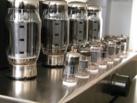
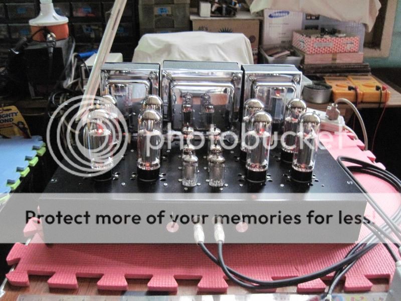
preliminary sound test....tubes are running at 26 watts per plate, G2 is mosfet regulated at 380 volts.....

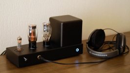
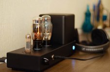
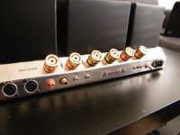
Hello, this is a headphone amp that I've built. It's the classic 6AS7G cathode follower OTL, with a few improvements.
The voltage amplifier is a E80CC (very nice tube), depletion mosFET CCS loaded, DC coupled to the cathode follower, which is also CCS loaded (bonus - the CCS avoids bias problems on startup).
The outputs are coupled through a pair of Mundorf MCap Oil + Audyn true copper to my 300 ohm HD650.
The PSU is a double (one for each channel) stabilized source follower with 2x10µ MKP on the output. The rectifier is a russian Svetlana 5Tz3S (5Ц3С). B+ is delayed by a 555 timer.
The 6.3v heaters are supplied by a small 4A soft-start switching PSU.
Attachments
Member
Joined 2009
Paid Member
Hello, this is a headphone amp that I've built. It's the classic 6AS7G cathode follower OTL, with a few improvements.
The voltage amplifier is a E80CC (very nice tube), depletion mosFET CCS loaded, DC coupled to the cathode follower, which is also CCS loaded (bonus - the CCS avoids bias problems on startup).
The outputs are coupled through a pair of Mundorf MCap Oil + Audyn true copper to my 300 ohm HD650.
The PSU is a double (one for each channel) stabilized source follower with 2x10µ MKP on the output. The rectifier is a russian Svetlana 5Tz3S (5Ц3С). B+ is delayed by a 555 timer.
The 6.3v heaters are supplied by a small 4A soft-start switching PSU.
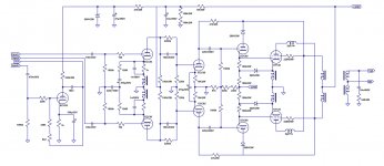
Marvellous! Can you kindly show us a circuit diagram? We are curious.
Marvellous! Can you kindly show us a circuit diagram? We are curious.
Sure, here is the diagram.
I must say that while it sounds good, I rather prefer the sound of my transformer output headphone amps.
Attachments
Hi guys,
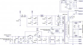
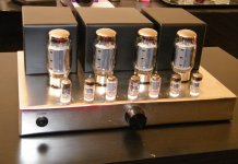
since there was no McIntosh MC275 clone on the web (at least I think so) I have decided to build one from cratch
Schematic is some kind of MKIV version of this amp with some modifications and inproovements, meaning that it is full-symetric from input to it's output even including full-symetric global feedback implemented to cathodes of the first stage. I have used 4xKT120's Tung-Sol for the output stage, 4xECC85 Tesla (12AT7) for driver followers and amplitude driver stage and 3xECC803S from JJ for pre-amp stage. The biggest problem was output transformer design, because there was very little information regarding this issue on the web, so after few months of study how this whole thing works I calculated a lot and designed mine own output transformer from scratch for this purpose.
Output transformer includes 2 bifillarly winded abosolutely separated symetric primary windings with Raa=750R winded with dual isolated wire to handle 500V DC potential that is between these wires. Because of price and simplicity it has only three sections of primary interleaved with two secondary sections and two feedback winding sections. The feedback winding is winded bifillarly and connected symetricaly for better "covering" whole surface of the winding for handling the high frequency characteristics with both halves of the symetric sine wave of feedback. (high frequencies transmitts not so much throught transformer core than through local electromagnetism on the surface of the wire). Secondary section is standard with 8R and 16R taps. The transformer core is 40x40mm made of high grade silicon steel.
Measured technical parameters:
RMS Power = 100W (one channel driven) or 2x72W (both channels driven in stereo mode)
Total THD = below 0,1% until approx. 25W, 0,18% for 50W @ 1kHz.
Frequency response 20Hz-20kHz with no drop over the range (maybe +-1dB max.). I was unable to measure higher frequencies due my hardware. I will measure this somewhere else at least for 100kHz, because I am very curious how far this amp can go...
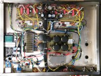
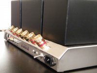
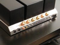
Below you can see some pics of the amp enjoy!
since there was no McIntosh MC275 clone on the web (at least I think so) I have decided to build one from cratch
Schematic is some kind of MKIV version of this amp with some modifications and inproovements, meaning that it is full-symetric from input to it's output even including full-symetric global feedback implemented to cathodes of the first stage. I have used 4xKT120's Tung-Sol for the output stage, 4xECC85 Tesla (12AT7) for driver followers and amplitude driver stage and 3xECC803S from JJ for pre-amp stage. The biggest problem was output transformer design, because there was very little information regarding this issue on the web, so after few months of study how this whole thing works I calculated a lot and designed mine own output transformer from scratch for this purpose.
Output transformer includes 2 bifillarly winded abosolutely separated symetric primary windings with Raa=750R winded with dual isolated wire to handle 500V DC potential that is between these wires. Because of price and simplicity it has only three sections of primary interleaved with two secondary sections and two feedback winding sections. The feedback winding is winded bifillarly and connected symetricaly for better "covering" whole surface of the winding for handling the high frequency characteristics with both halves of the symetric sine wave of feedback. (high frequencies transmitts not so much throught transformer core than through local electromagnetism on the surface of the wire). Secondary section is standard with 8R and 16R taps. The transformer core is 40x40mm made of high grade silicon steel.
Measured technical parameters:
RMS Power = 100W (one channel driven) or 2x72W (both channels driven in stereo mode)
Total THD = below 0,1% until approx. 25W, 0,18% for 50W @ 1kHz.
Frequency response 20Hz-20kHz with no drop over the range (maybe +-1dB max.). I was unable to measure higher frequencies due my hardware. I will measure this somewhere else at least for 100kHz, because I am very curious how far this amp can go...
Below you can see some pics of the amp
enjoy!Attachments
That is an awesome build Wiliks!
How long did it take you from start to finish? And would you do it all over again? And if you did, would you change anything? Just curious because I haven't seen anything like this here or nearly anywhere else.
How long did it take you from start to finish? And would you do it all over again? And if you did, would you change anything? Just curious because I haven't seen anything like this here or nearly anywhere else.
Hi guys,
since there was no McIntosh MC275 clone on the web (at least I think so) I have decided to build one from cratch
Schematic is some kind of MKIV version of this amp with some modifications and inproovements, meaning that it is full-symetric from input to it's output even including full-symetric global feedback implemented to cathodes of the first stage. I have used 4xKT120's Tung-Sol for the output stage, 4xECC85 Tesla (12AT7) for driver followers and amplitude driver stage and 3xECC803S from JJ for pre-amp stage. The biggest problem was output transformer design, because there was very little information regarding this issue on the web, so after few months of study how this whole thing works I calculated a lot and designed mine own output transformer from scratch for this purpose.
Output transformer includes 2 bifillarly winded abosolutely separated symetric primary windings with Raa=750R winded with dual isolated wire to handle 500V DC potential that is between these wires. Because of price and simplicity it has only three sections of primary interleaved with two secondary sections and two feedback winding sections. The feedback winding is winded bifillarly and connected symetricaly for better "covering" whole surface of the winding for handling the high frequency characteristics with both halves of the symetric sine wave of feedback. (high frequencies transmitts not so much throught transformer core than through local electromagnetism on the surface of the wire). Secondary section is standard with 8R and 16R taps. The transformer core is 40x40mm made of high grade silicon steel.
Measured technical parameters:
RMS Power = 100W (one channel driven) or 2x72W (both channels driven in stereo mode)
Total THD = below 0,1% until approx. 25W, 0,18% for 50W @ 1kHz.
Frequency response 20Hz-20kHz with no drop over the range (maybe +-1dB max.). I was unable to measure higher frequencies due my hardware. I will measure this somewhere else at least for 100kHz, because I am very curious how far this amp can go...
Below you can see some pics of the amp
Thanks
It took whole about 4 months, I mean all from designing things to realisation. Some things went faster - some slower, because I had to wait sometimes to get parts etc. Probably took longer also because I was doing it over evenings after my work...
And yes, If I had time, I would do it over again but probably I would change some things. I have used only 400W toroid transformer, which is obviously not enough for max power (I used that one because I already had it from another amp). Also my transformer has symetrical secondary for anode voltage, this is also disadvantage that only rises internal resistance of the transformer so power is not so tought as it would be with only one non-symetric winding. Probably filter choke is too overboosted (1H/600mA), maybe better would be 0,5-0,8H / 800mA. Also stabilised heating power supply for small tubes with slow turn-on is very great high-end thingy, but it is kind of overkill and it just produces extra heat in chassis. Standard filtered psu without stabiliser would be enough for this purpose. And to the last, I would probably not do that via the same style as PCB-wire-socket style, but all-PCB style. Because it is really sick to wire so many sockets with PCB board and mainly the output tubes where are many wires not even between transformers but also between the sockets, so I think all-PCB solution would be probably better but more difficult to design PCB. But I didn't know if the amp would work or no, so my way is at least a bit better for some modification.
It took whole about 4 months, I mean all from designing things to realisation. Some things went faster - some slower, because I had to wait sometimes to get parts etc. Probably took longer also because I was doing it over evenings after my work...
And yes, If I had time, I would do it over again
but probably I would change some things. I have used only 400W toroid transformer, which is obviously not enough for max power (I used that one because I already had it from another amp). Also my transformer has symetrical secondary for anode voltage, this is also disadvantage that only rises internal resistance of the transformer so power is not so tought as it would be with only one non-symetric winding. Probably filter choke is too overboosted (1H/600mA), maybe better would be 0,5-0,8H / 800mA. Also stabilised heating power supply for small tubes with slow turn-on is very great high-end thingy, but it is kind of overkill and it just produces extra heat in chassis. Standard filtered psu without stabiliser would be enough for this purpose. And to the last, I would probably not do that via the same style as PCB-wire-socket style, but all-PCB style. Because it is really sick to wire so many sockets with PCB board and mainly the output tubes where are many wires not even between transformers but also between the sockets, so I think all-PCB solution would be probably better but more difficult to design PCB. But I didn't know if the amp would work or no, so my way is at least a bit better for some modification.
Last edited:
90w EL34 monoblocks
Hi
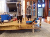
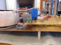
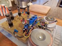
This is a new PCB gerber file conversion from old artwork, the boards are 2 oz copper tracks, with thick pcb board. This chassis is the 1st prototype board the rest will be put into a case for safety reasons.
Hi
This is a new PCB gerber file conversion from old artwork, the boards are 2 oz copper tracks, with thick pcb board. This chassis is the 1st prototype board the rest will be put into a case for safety reasons.
Attachments
-
 PA040001.jpg656.7 KB · Views: 548
 -
 PA040002.jpg613.5 KB · Views: 389
 -
 PA040003.jpg640.7 KB · Views: 360
 -
 PA040006.jpg729.4 KB · Views: 376
 -
 PA040005.jpg534.1 KB · Views: 315
 -
 PA040004.jpg647.7 KB · Views: 397
 -
 PA040007.jpg508.9 KB · Views: 359
 -
 PA040008.jpg536.1 KB · Views: 302
 -
 PA040009.jpg576.8 KB · Views: 305
 -
 PA040010.jpg478.2 KB · Views: 277
Hi guys,
since there was no McIntosh MC275 clone on the web (at least I think so) I have decided to build one from cratch
Schematic is some kind of MKIV version of this amp with some modifications and inproovements, meaning that it is full-symetric from input to it's output even including full-symetric global feedback implemented to cathodes of the first stage. I have used 4xKT120's Tung-Sol for the output stage, 4xECC85 Tesla (12AT7) for driver followers and amplitude driver stage and 3xECC803S from JJ for pre-amp stage. The biggest problem was output transformer design, because there was very little information regarding this issue on the web, so after few months of study how this whole thing works I calculated a lot and designed mine own output transformer from scratch for this purpose.
Output transformer includes 2 bifillarly winded abosolutely separated symetric primary windings with Raa=750R winded with dual isolated wire to handle 500V DC potential that is between these wires. Because of price and simplicity it has only three sections of primary interleaved with two secondary sections and two feedback winding sections. The feedback winding is winded bifillarly and connected symetricaly for better "covering" whole surface of the winding for handling the high frequency characteristics with both halves of the symetric sine wave of feedback. (high frequencies transmitts not so much throught transformer core than through local electromagnetism on the surface of the wire). Secondary section is standard with 8R and 16R taps. The transformer core is 40x40mm made of high grade silicon steel.
Measured technical parameters:
RMS Power = 100W (one channel driven) or 2x72W (both channels driven in stereo mode)
Total THD = below 0,1% until approx. 25W, 0,18% for 50W @ 1kHz.
Frequency response 20Hz-20kHz with no drop over the range (maybe +-1dB max.). I was unable to measure higher frequencies due my hardware. I will measure this somewhere else at least for 100kHz, because I am very curious how far this amp can go...
Below you can see some pics of the amp
Perfect project, i hope the sound as perfect as the project
Congratulation
Thanks
This is a new PCB
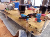
I like it, it's neat and tidy. The bias bar graph is a nice touch. I would probably have used cermet trimmers for bias adjusting, they are more reliable.
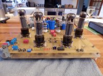
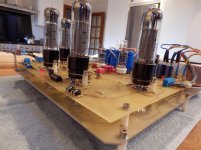
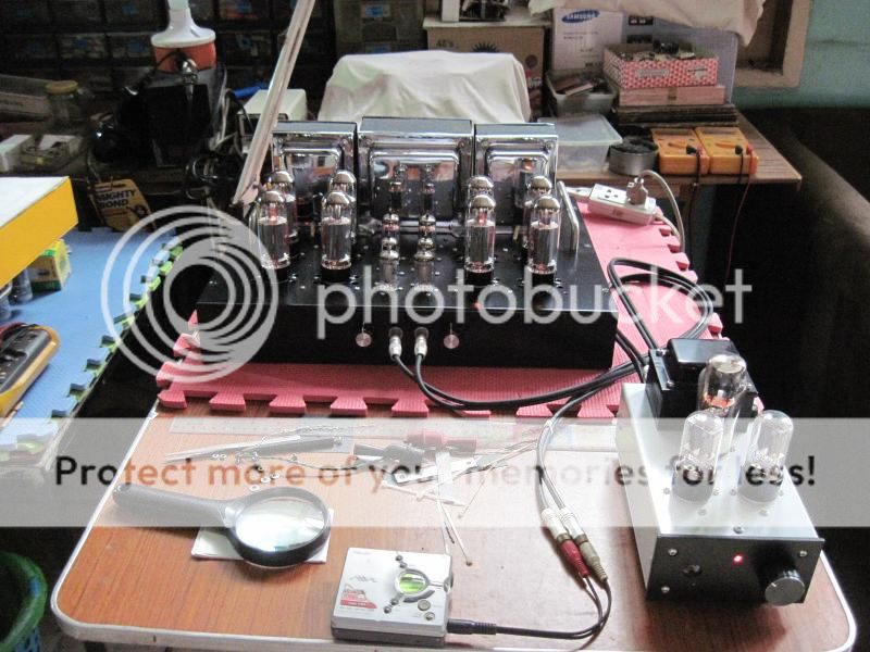
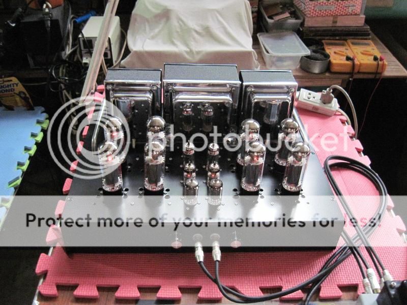
now playing......EL34 parallel push-pull inspired my Marantz 9 monos...
uses the A431 OPT copy.....
input is a 6J32/EF86 pentode, then the 6RRH8 LTP phase splitter driving a 6CG7 cathode followers....
now tweaking to resolve some minor issues.....
preamp is a CCDA 6H8C/6SN7 fed from my MD player playing Bread songs...
uses the A431 OPT copy.....
input is a 6J32/EF86 pentode, then the 6RRH8 LTP phase splitter driving a 6CG7 cathode followers....
now tweaking to resolve some minor issues.....
preamp is a CCDA 6H8C/6SN7 fed from my MD player playing Bread songs...


Measured technical parameters:
RMS Power = 100W (one channel driven) or 2x72W (both channels driven in stereo mode)
Total THD = below 0,1% until approx. 25W, 0,18% for 50W @ 1kHz.
Frequency response 20Hz-20kHz with no drop over the range (maybe +-1dB max.). I was unable to measure higher frequencies due my hardware. I will measure this somewhere else at least for 100kHz, because I am very curious how far this amp can go...
Good work:-some questions:
KT120 for the power you quote, these tubes are hardly being tickled ? Your reason for choosing them ?
Can you explain the reason behind the power drop with both channels driven in stereo mode ?
The response...maybe a 1dB rise at 20KHz ?...If so, the figure at 50kHz needs checking out.
richy
richwalters - regarding the lower power in stereo mode:
Maybe that issue above, or low filter capacity. I have used there only 235uF before and after choke. Probably increasing the filter capacitors value could improve power significantly. I am going to tune this in future, just I have to find the right capacitors
Regarding using the KT120... I have used them, because there was not big price difference between KT88 and KT120, so I decided to buy the better ones. Their max power in AB could be about 150W, so yes they are just "idling" even at max power but I like to overpower things, at least I know they will have loooong life.
Regarding your frequency question... what I tested was off course the whole frequency range with oscilloscope. I was just saying, that I can't proove what exactly is the frequency response right now because I can't measure this very accurately at home. But at least from my "home" measures it looks like -3dB @ 50kHz at full power. This goes very nicely linearly down and ends somewhere at 200-300kHz. with no resonant peaks at all or something that is common in standard output transformers. And yes there were HF issues with this amp, even after tweaking global negative feedback with right capacitor values, it was oscillating 1V@1Mhz on the output. I have solved this with boucherot cell. After compensations it is nice and fully stable, and even square wave is nice and quite crispy
And so there is about 100V drop at the output of power supply when amp is draining full power.I have used only 400W toroid transformer, which is obviously not enough for max power (I used that one because I already had it from another amp). Also my transformer has symetrical secondary for anode voltage, this is also disadvantage that only rises internal resistance of the transformer so power is not so tought as it would be with only one non-symetric winding. Probably filter choke is too overboosted (1H/600mA), maybe better would be 0,5-0,8H / 800mA.
Maybe that issue above, or low filter capacity. I have used there only 235uF before and after choke. Probably increasing the filter capacitors value could improve power significantly. I am going to tune this in future, just I have to find the right capacitors
Regarding using the KT120... I have used them, because there was not big price difference between KT88 and KT120, so I decided to buy the better ones. Their max power in AB could be about 150W, so yes they are just "idling" even at max power
but I like to overpower things, at least I know they will have loooong life.Regarding your frequency question... what I tested was off course the whole frequency range with oscilloscope. I was just saying, that I can't proove what exactly is the frequency response right now because I can't measure this very accurately at home. But at least from my "home" measures it looks like -3dB @ 50kHz at full power. This goes very nicely linearly down and ends somewhere at 200-300kHz. with no resonant peaks at all or something that is common in standard output transformers. And yes there were HF issues with this amp, even after tweaking global negative feedback with right capacitor values, it was oscillating 1V@1Mhz on the output. I have solved this with boucherot cell. After compensations it is nice and fully stable, and even square wave is nice and quite crispy
I like it, it's neat and tidy. The bias bar graph is a nice touch. I would probably have used cermet trimmers for bias adjusting, they are more reliable.
Hi Good advice .. I will do this on the next build
regards
I would probably have used cermet trimmers for bias adjusting, they are more reliable.
Absolutely, I've used these for years on tube amplifiers and never had a problem. They're very stable, too.
More reliable than what? wire wound?
Where can you buy cermet's the only ones I have seen are tiny.Can you buy good quality ones?
Hi, multiturn cermet trimmers are better than the conductive plastic single turn ones. The tiny cermets are very good for adjusting fixed bias.
There are bigger, panel-mount ones available, but they are very expensive.
Wirewound pots shouldn't be used for fixed bias.
I have used there only 235uF before and after choke. Probably increasing the filter capacitors value could improve power significantly. I am going to tune this in future, just I have to find the right capacitors
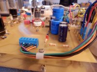
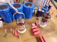
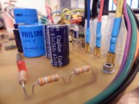
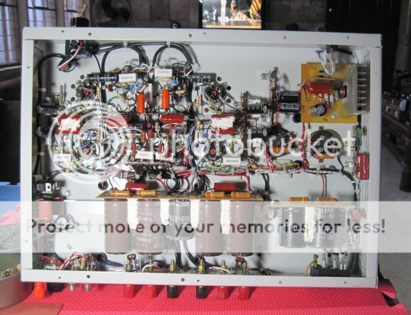
this is the ones i used in my recent 6550 build, series connected Nichicon 105*C. 1100/300vdc caps...translated to 550uf/600vdc caps...
An externally hosted image should be here but it was not working when we last tested it.
- Home
- Amplifiers
- Tubes / Valves
- Photo Gallery