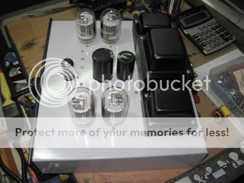
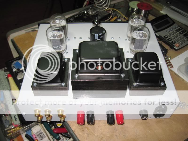
A nice shiny new DIYTube Get Set Go with Transcendar OPTs and a Triode Electronics power transformer.
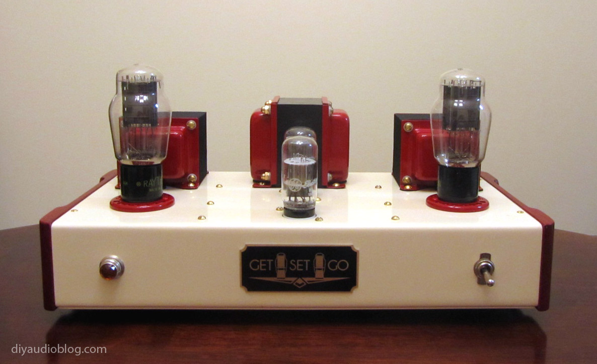
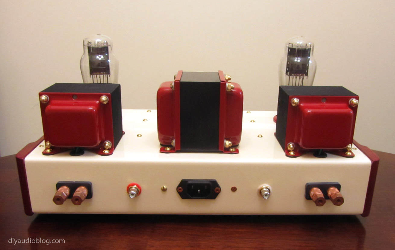
Visit here for more lots more photos and details: DIY Audio Electronics from Zynsonix.com: DIYTube Get*Set*Go Single Ended Amplifier
Visit here for more lots more photos and details: DIY Audio Electronics from Zynsonix.com: DIYTube Get*Set*Go Single Ended Amplifier
'True love lives' amp
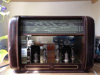
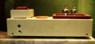
Here is an amp I built for a friends wedding present. It is an old bakerlight radio, gutted then a EL84 PP amp built inside. Engraved on the front is a lyric from Radiohead - True love waits and the date.
It sounds good, not amazing but good enough for a gift I think. And it took quite a while to get it all together - I thought my metal work was bad, it turns out my wood work is even worse! It is a little rough around the edges to say the least.
Right, now that is done I can finally get to work on my #26 preamp. I really don't know where you guys get the time for all your projects, you must all be retired!
Cheers
Charlie
Here is an amp I built for a friends wedding present. It is an old bakerlight radio, gutted then a EL84 PP amp built inside. Engraved on the front is a lyric from Radiohead - True love waits and the date.
It sounds good, not amazing but good enough for a gift I think. And it took quite a while to get it all together - I thought my metal work was bad, it turns out my wood work is even worse!
It is a little rough around the edges to say the least.Right, now that is done I can finally get to work on my #26 preamp. I really don't know where you guys get the time for all your projects, you must all be retired!
Cheers
Charlie
Attachments
A nice shiny new DIYTube Get Set Go with Transcendar OPTs and a Triode Electronics power transformer.
Visit here for more lots more photos and details: DIY Audio Electronics from Zynsonix.com: DIYTube Get*Set*Go Single Ended Amplifier
Love the colour combinations and the art deco logo! Which wood for the cheeks?
my first 6GK6 classA pp amp build:
An externally hosted image should be here but it was not working when we last tested it.
An externally hosted image should be here but it was not working when we last tested it.
An externally hosted image should be here but it was not working when we last tested it.
Hope they thanked you for such a fine gift.
Thank you. Wedding is next weekend, I will be very glad to see the back of it!
Better give it one last clean before it gets packed up.
Attachments
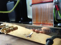
Here is an amp I built for a friends wedding present. It is an old bakerlight radio, gutted then a EL84 PP amp built inside. Engraved on the front is a lyric from Radiohead - True love waits and the date.
It sounds good, not amazing but good enough for a gift I think. And it took quite a while to get it all together - I thought my metal work was bad, it turns out my wood work is even worse!
Right, now that is done I can finally get to work on my #26 preamp. I really don't know where you guys get the time for all your projects, you must all be retired!
Cheers
Charlie
Very cool
.Cheers
Thanks, It's walnut, stained with some water-based red dye.Love the colour combinations and the art deco logo! Which wood for the cheeks?
Beautiful amplifier Charlie! What a great wedding gift!
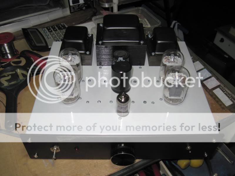
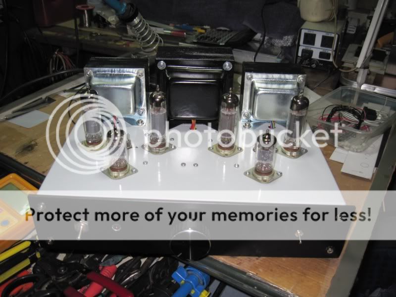
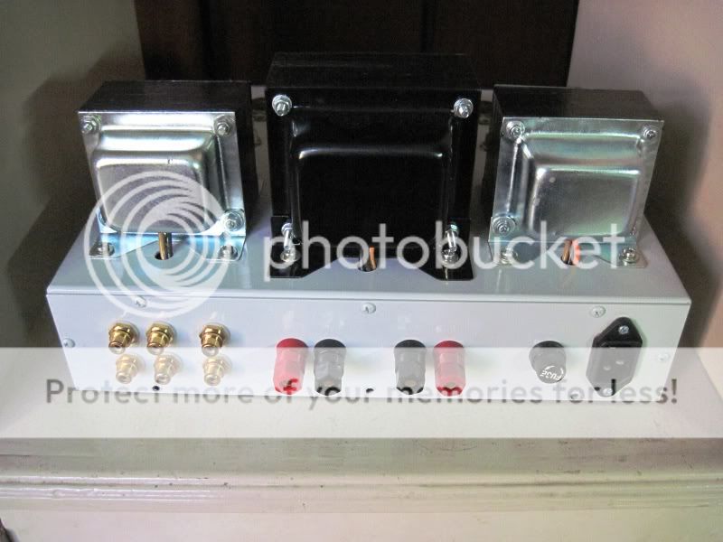
2 x 10 W PP with QQE03/12
I built a prototype with a pair of QQE03/12 double tetrodes and pair of soviet 6F12P triode-pentode (which is a phenomenal tube).
Voltage amplifying stage is a CCS loaded triode and phase splitter is done with pentode section of 6F12P. Output stage has fixed bias and 10k to 8 ohms Indel output transformer.
Anode voltage is 300 V and screen voltage 220 V. Both bias and screen supply are stabilized. Output power is 10 W with 1 % THD. With one watt THD is some 0.1...0.2 % with 10 dB GNFB.
Input sensitivity is 600 mV. Hum level at the output is some 80 dB below max. Po. All heaters are done with AC.
An externally hosted image should be here but it was not working when we last tested it.
An externally hosted image should be here but it was not working when we last tested it.
An externally hosted image should be here but it was not working when we last tested it.
Amazing
I built a prototype with a pair of QQE03/12 double tetrodes and pair of soviet 6F12P triode-pentode (which is a phenomenal tube).
Voltage amplifying stage is a CCS loaded triode and phase splitter is done with pentode section of 6F12P. Output stage has fixed bias and 10k to 8 ohms Indel output transformer.
Anode voltage is 300 V and screen voltage 220 V. Both bias and screen supply are stabilized. Output power is 10 W with 1 % THD. With one watt THD is some 0.1...0.2 % with 10 dB GNFB.
Input sensitivity is 600 mV. Hum level at the output is some 80 dB below max. Po. All heaters are done with AC.
An externally hosted image should be here but it was not working when we last tested it.
Right now I trying to do some like this, beautiful finish. The PCB.
Nice election (couse i did the same) Can you publish the diagram?
Congratulations again
An externally hosted image should be here but it was not working when we last tested it.
An externally hosted image should be here but it was not working when we last tested it.

Diagram for the QQE PP amp.
Here it comes:
Here it comes:
An externally hosted image should be here but it was not working when we last tested it.
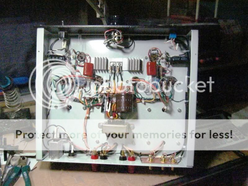
Supply voltage at the anodes of QQE02/12 is some 300...310 V. Optimum screen supply is about 220 V and quiescent anode current 30...32 mA.
CCS transistors are BF472 (PNP) and the NFET at power supply is IRF820.
Direct coupling of the voltage amplifying stage and phase splitter requires that the anode voltage of 1st stage should be some 80 V. The circuit I used give lower distortion.
I did not try to use pentode as 1st stage since the gain of triode section (mu = 100 ) was just what I needed. But ofcourse the pentode would work fine as an amplifier.
- Home
- Amplifiers
- Tubes / Valves
- Photo Gallery