Hi everyone,
My Tocatta preamp is coming together nicely (PS finished and one channel done) and I'm starting to think about an amp project. I have a JEL 300b so I want to try something else next. My listening room is small (12 x9), my Fostex 208 are sensitive enough, so I don't need a lot of power.
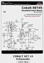
What are your thoughts about this amp? I will probably tube rectify the PS and use oil caps, but keep everything else the same.
thanks
jonathan
Attachments
I was not able to expand the image enough to read component values but I do like the idea of parafeed and ultrapath output coupling which was about all I could determine from LEO. This is definitely not your Grandfather's 45 amp.
Can you post a higher resolution schematic? My 'good' spy satellite that can read liscense plate numbers from orbit is in the shop for repairs.
Can you post a higher resolution schematic? My 'good' spy satellite that can read liscense plate numbers from orbit is in the shop for repairs.
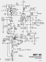
Here's a better schematic (I think). It comes from the Magnequest site (http://www.magnequest.com/diy/strain/SE45schem3.gif).
Jonathan
Jonathan
Attachments
I used a similar concept when I designed my 45SE amplifier, except that I used conventional Electra-Print output transformers. If you do a parafeed design you should use a transformer - choke pair that were designed to work with the 45. This schematic specifies the "Cobalt" series from Magnequest.
I experimented with the bipolar transistor CCS design that is used here, and I believe that the IXYS 10M45 chip sounds better. The parts are cheap (compared to the rest of the circuit) so you may want to try both CCS circuits. I tried several different input tubes before settling on the 5842. I did not try the 6H30, since I didn't have any. That was several years ago, before the 5842 became a "boutique tube" and they were cheap.
I also prefer the sound of a tube rectifier, so I used a 5AR4.
Over about a year of time and tinkering, my circuit evolved into something quite different. It is now a conventional grounded cathode output stage with fixed bias using a PowerDrive circuit. Even though I use the PowerDrive in most of my designs, I must admit that it doesn't buy you much with a 45, since most 45's are nonlinear way before the grid can draw any current.
I used a 47uF 20 volt tantalum cap, primarilly becasuse I had a bunch of them. My experience with tantalum caps has been good. They have a low ESR well up into the VHF region. For low voltage capacitors I would use a tantalum before I even thought of an electrolytic. The only other choice would be a monolithic ceramic cap, and I would feel paranoid about those, they tend to be piezoelectric, which translates to microphonics in this case.
We used tantalums in cell phones up until they became scarce about 5 or 6 years ago. The prices for large quantities of tantalum caps went from 10 cents each to over a dollar each. They have been replaced in the phone world by large value monolithic ceramic caps. Now that the phone makers of the world have abandoned tantalums, the prices have returned to almost normal.
We used tantalums in cell phones up until they became scarce about 5 or 6 years ago. The prices for large quantities of tantalum caps went from 10 cents each to over a dollar each. They have been replaced in the phone world by large value monolithic ceramic caps. Now that the phone makers of the world have abandoned tantalums, the prices have returned to almost normal.
- Status
- This old topic is closed. If you want to reopen this topic, contact a moderator using the "Report Post" button.

