Hello friends!
It's time to decide something about the RIAA stage in my preamplifier. I've already prototiped one of the circuits below, the Audio Innovations one and I'm quite satisfied.
Btw B+ is at 220V regulated.
Here is a little confrontation about RIAA and phono stages:
The respective circuits are those:
Audio Innovations one - blue line
Kevin R. Kennedy's phonostage - black line
Thoersten's phonostage - red line
(image attached below)
A phonostage, from Construire Hi-Fi (by kind permission of Andrea Bassanelli, Blu Press) - yellow line
So what do you think? What's the best RIAA curve, what's the best circuit?
It's time to decide something about the RIAA stage in my preamplifier. I've already prototiped one of the circuits below, the Audio Innovations one and I'm quite satisfied.
Btw B+ is at 220V regulated.
Here is a little confrontation about RIAA and phono stages:
An externally hosted image should be here but it was not working when we last tested it.
The respective circuits are those:
An externally hosted image should be here but it was not working when we last tested it.
Audio Innovations one - blue line
An externally hosted image should be here but it was not working when we last tested it.
Kevin R. Kennedy's phonostage - black line
An externally hosted image should be here but it was not working when we last tested it.
Thoersten's phonostage - red line
(image attached below)
A phonostage, from Construire Hi-Fi (by kind permission of Andrea Bassanelli, Blu Press) - yellow line
So what do you think? What's the best RIAA curve, what's the best circuit?
Attachments
Ehm.... the problem is that I don't know how to do it 
I made the graph by copying the simulation results from Multisim, and paste one on top of the other.
If it would be possible I'd have done it")
Maybe if I transport everything to Excel... but how?
(even aside from that, shame on me )
)
I made the graph by copying the simulation results from Multisim, and paste one on top of the other.
If it would be possible I'd have done it
Maybe if I transport everything to Excel... but how?
(even aside from that, shame on me
)Here, this shows the poles and zeros, also has links to excel...
http://www.euronet.nl/~mgw/background/riaa/uk_riaa_background_1.html
Goto Page 2 and you will see a passive circuit that you can simulate... you may have to add some perfect gain to adjust the overall dB
Kepp in mind the difference between "Classic" RIAA and "new IEC" RIAA. The difference, like what you have posted, is mostly about RUMBLE filtering
Here's the results of the simulation of the circuit in figure 2.3 in page 2, poobah:
It doesn't look like a RIAA
http://www.diyaudio.com/forums/showthread.php?s=&threadid=28957
isn't it this phono pre (on the bottom of the first page)? Wait, does Thoersten nick = Kuei or am I wrong?
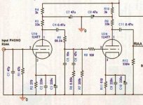
The circuit I've simulated would be the adaption for using ECC83 even in the second stage, as SY and others suggested me in this thread http://www.diyaudio.com/forums/showthread.php?s=&threadid=69404
An externally hosted image should be here but it was not working when we last tested it.
It doesn't look like a RIAA
analog_sa said:Thorsten has an ECC83 phono?
http://www.diyaudio.com/forums/showthread.php?s=&threadid=28957
isn't it this phono pre (on the bottom of the first page)? Wait, does Thoersten nick = Kuei or am I wrong?
The circuit I've simulated would be the adaption for using ECC83 even in the second stage, as SY and others suggested me in this thread http://www.diyaudio.com/forums/showthread.php?s=&threadid=69404
Giame,
The first pole (lowpass 50 Hz) and the first zero (high pass 500 Hz) look good. The second pole (low pass 2212 Hz) looks bad because of loading from the first stage. You need a buffer between the 2 stages ( Perfect Buffer; Zin = infinity, Gain = 1, Zout = 0).
Remember this is not a real circuit... just a way to make the curve.
Use figure 2.2 and insert a perfect amplifier with gain = 1 between section 1 and 2...
Also see page 1 there is an excel spreadsheet with the RIAA..
Thank you poobah, I'm a bad student
How do I implement a perfect amp? I've tried an opamp with the output tied to the - input, but nothing, even a voltage-controlled voltage source, nothing, I tried a voltage controlled current source (transconductance 0.3mMho to get the proper gain) and the result is strange...
How do I implement a perfect amp? I've tried an opamp with the output tied to the - input, but nothing, even a voltage-controlled voltage source, nothing, I tried a voltage controlled current source (transconductance 0.3mMho to get the proper gain) and the result is strange...
Attachments
Giaime,
If you use a 'X7 section in the 2nd gain block, instead of a 6922 section, you have to deal with very limited drive capability. The seminal RCA circuit has the problem too.
Is your phono section going to be part of a full function preamp, where the poor drive capability of the 'X7 is of minimal concern?
Konnichiwa,
May I suggest that to "adapt" the circuit to use a ECC83, led biased in the second stage instead of the gridleak biased ECC88 is a monumentally bad idea. If I had thought an ECC83 apropriate, I would have used one. If you don't like my circuit as designed, I suggest you simply build something else, instead of messing up a perfectly servicable and decent design with questionable "adaptations".
Sayonara
Giaime said:http://www.diyaudio.com/forums/showthread.php?s=&threadid=28957
isn't it this phono pre (on the bottom of the first page)? Wait, does Thoersten nick = Kuei or am I wrong?
May I suggest that to "adapt" the circuit to use a ECC83, led biased in the second stage instead of the gridleak biased ECC88 is a monumentally bad idea. If I had thought an ECC83 apropriate, I would have used one. If you don't like my circuit as designed, I suggest you simply build something else, instead of messing up a perfectly servicable and decent design with questionable "adaptations".
Sayonara
Konnichiwa,
If he is so short that he cannot afford a single ECC88 he may wish to build something else. The combination of '88 & '83 is essential to the way my Phonostage sounds.
Neither Valve if repeated (two '88's or two '83's in series) makes for good sound, in fact they both make for fairly poor sound on their own, but their sonic faults are largely complementary, which is why it works so well.
I am sure Giaime can find a single ECC88/6DJ8 for very little money, if he looks a little. It is really worth doing.
Sayonara
poobah said:He is a student working only with the parts he has.
If he is so short that he cannot afford a single ECC88 he may wish to build something else. The combination of '88 & '83 is essential to the way my Phonostage sounds.
Neither Valve if repeated (two '88's or two '83's in series) makes for good sound, in fact they both make for fairly poor sound on their own, but their sonic faults are largely complementary, which is why it works so well.
I am sure Giaime can find a single ECC88/6DJ8 for very little money, if he looks a little. It is really worth doing.
Sayonara
Konnichiwa,
The Schematic is the one attached to this post:
http://www.diyaudio.com/forums/showthread.php?postid=335624#post335624
ALL Values are accurate, there are NO errors, no changes needed and performance is as indicated. Resistoirs with "odd" values are RC55 0.1% tolerance ones.
Gain is > 40db, with "bogey" valves 42db into a 100K Load, 20Hz - 20KHz +/-0.1db RIAA accuracy into 100K.
With a 10K load 20Hz are down by 0.6db and gain is down to 39.5db.
Sayonara
poobah said:Please post or link to your proper schematic... I think there is some confusion here.
The Schematic is the one attached to this post:
http://www.diyaudio.com/forums/showthread.php?postid=335624#post335624
ALL Values are accurate, there are NO errors, no changes needed and performance is as indicated. Resistoirs with "odd" values are RC55 0.1% tolerance ones.
Gain is > 40db, with "bogey" valves 42db into a 100K Load, 20Hz - 20KHz +/-0.1db RIAA accuracy into 100K.
With a 10K load 20Hz are down by 0.6db and gain is down to 39.5db.
Sayonara
Here's the link
http://www.diyaudio.com/forums/attachment.php?s=&postid=335624&stamp=1077837811
Poobah, Santa hasn't arrived but we will see about that option.
Eli, thank you very much. I understand your question, but the second stage of the phono preamp will be coupled with a 12AT7 cathode follower in the same preamp, the schematic is on my site. So it hasn't to drive any load (other than 100k volume pot).
Thank you Kuei Yang Wang, I expected a bit more kind replies, but your suggestions are always welcome. By the way, LED biasing was suggested by a person that isn't a newbie: http://www.diyaudio.com/forums/showthread.php?postid=787372#post787372
However, thanks to everyone.
http://www.diyaudio.com/forums/attachment.php?s=&postid=335624&stamp=1077837811
Poobah, Santa hasn't arrived
but we will see about that option.Eli, thank you very much. I understand your question, but the second stage of the phono preamp will be coupled with a 12AT7 cathode follower in the same preamp, the schematic is on my site.
So it hasn't to drive any load (other than 100k volume pot).Thank you Kuei Yang Wang, I expected a bit more kind replies, but your suggestions are always welcome. By the way, LED biasing was suggested by a person that isn't a newbie: http://www.diyaudio.com/forums/showthread.php?postid=787372#post787372
However, thanks to everyone.
Konnichiwa,
I would not know about the person and could not care less.
At 1mA or less current the LED will be in a very non-linear range of it's curve, at the same time the output stage will swing quite a bit of current so this non-linearity becomes very relevant and will likely be much higher than the ECC83 alone will be. It is a REALLY TERRIBLE idea.
You could help by adding a CCS driving an extra 10-20mA into the LED to get it into a more linear region, but listening tests (and not just my own ones) suggest LED biasing as the worst possibvle solution, followed by cathode biasing using electrolytic bypass capacitors.
Using an unbypassed cathode resistor is generally best but results in a lower gain and increased output impedance so while it is a great solution in the input stage which also helps leveling out differences between valves, but in the output stage it is wholly inapropriate.
One could use fixed gridbias, but this edds a lot of complications that are not neccesary when using gridleak bias.
Let me repeat, my design is what it is for good reasons.
EVERY single part of the design uses the optimal solution within the fundamental constraints, which where 2 Valves and using common, readily available current production types and low general cost, in other words minimal num bers of expensive parts.
To mertially improve upon this you must go for a very different approach, use less readily available valves and different topologies.
Sayonara
Giaime said:By the way, LED biasing was suggested by a person that isn't a newbie: http://www.diyaudio.com/forums/showthread.php?postid=787372#post787372
I would not know about the person and could not care less.
At 1mA or less current the LED will be in a very non-linear range of it's curve, at the same time the output stage will swing quite a bit of current so this non-linearity becomes very relevant and will likely be much higher than the ECC83 alone will be. It is a REALLY TERRIBLE idea.
You could help by adding a CCS driving an extra 10-20mA into the LED to get it into a more linear region, but listening tests (and not just my own ones) suggest LED biasing as the worst possibvle solution, followed by cathode biasing using electrolytic bypass capacitors.
Using an unbypassed cathode resistor is generally best but results in a lower gain and increased output impedance so while it is a great solution in the input stage which also helps leveling out differences between valves, but in the output stage it is wholly inapropriate.
One could use fixed gridbias, but this edds a lot of complications that are not neccesary when using gridleak bias.
Let me repeat, my design is what it is for good reasons.
EVERY single part of the design uses the optimal solution within the fundamental constraints, which where 2 Valves and using common, readily available current production types and low general cost, in other words minimal num bers of expensive parts.
To mertially improve upon this you must go for a very different approach, use less readily available valves and different topologies.
Sayonara
- Status
- This old topic is closed. If you want to reopen this topic, contact a moderator using the "Report Post" button.
- Home
- Amplifiers
- Tubes / Valves
- Giaime's last nightmare - aka RIAA faceoff