Thank you Thoersten,
I really appreciate your work and I'm not criticizing it in any way. I was trying to "go around" the need of an ECC88 which I don't have in my parts bin: I'm sure that's a suboptimal solution.
When I'll get the proper tube, I'll hear how good is the work you've done")
By the way, the choice of not cutting the bass below 10Hz is dictated by the presumption that a good turntable doesn't rumble? Or there's more deep problem in it?
I really appreciate your work and I'm not criticizing it in any way. I was trying to "go around" the need of an ECC88 which I don't have in my parts bin: I'm sure that's a suboptimal solution.
When I'll get the proper tube, I'll hear how good is the work you've done
By the way, the choice of not cutting the bass below 10Hz is dictated by the presumption that a good turntable doesn't rumble? Or there's more deep problem in it?
Konnichiwa,
No, but any LED would overbias the stage considerably and given the lower anode load we also see more current swing in the anode circuit and we are back where we where with the LED's non-linearity asserting itself as a dominant or at least very substantial factor.
The protestations of a number of people nonwithstanding, LED Bias is generally a VERY BAD idea. The only time when it is not is in a situation where no signal current swing occurs under normal conditions, that means with constant current anode load and when direct coupling into another valve or at least using a very high impedance loads.
Basically, if the signal levels are sufficiently low (as they are in a phonostage) gridleak biasing is by far the superior methode, objectively and subjectively.
So, for my ECC88 Stage in my Phono stage LED Bias is inapropriate, for the ECC83 as drawn in the schematic on page 1 LED Bias is inaproriate. In virtually any usual application LED Bias is inaproriate.
It has possible uses, but they are VERY limited and great care is needed in implementation, allowing a general blanket statement of "LED Bias is inaproriate for tube circuits" with a corollary of "Under some specific circumstances LED Biasing may be apropriate but no better than other methodes.".
Sayonara
SY said:Note that my suggestion was for the LED on the ECC88 stage. That one isn't running 1 mA, is it?
No, but any LED would overbias the stage considerably and given the lower anode load we also see more current swing in the anode circuit and we are back where we where with the LED's non-linearity asserting itself as a dominant or at least very substantial factor.
The protestations of a number of people nonwithstanding, LED Bias is generally a VERY BAD idea. The only time when it is not is in a situation where no signal current swing occurs under normal conditions, that means with constant current anode load and when direct coupling into another valve or at least using a very high impedance loads.
Basically, if the signal levels are sufficiently low (as they are in a phonostage) gridleak biasing is by far the superior methode, objectively and subjectively.
So, for my ECC88 Stage in my Phono stage LED Bias is inapropriate, for the ECC83 as drawn in the schematic on page 1 LED Bias is inaproriate. In virtually any usual application LED Bias is inaproriate.
It has possible uses, but they are VERY limited and great care is needed in implementation, allowing a general blanket statement of "LED Bias is inaproriate for tube circuits" with a corollary of "Under some specific circumstances LED Biasing may be apropriate but no better than other methodes.".
Sayonara
Konnichiwa,
Well, you can get a variety of ECC88 equivalent Valves from around 7 Euro upwards.... I think that is to "go around" too far.
If your turntable rumbles you have serious problems. You need to fix these first.
Group delay is very audible at low frequencies, there already accumulates a lot of group delay in a variety of devices, no more is needed.
Sayonara
Giaime said:I was trying to "go around" the need of an ECC88 which I don't have in my parts bin:
Well, you can get a variety of ECC88 equivalent Valves from around 7 Euro upwards.... I think that is to "go around" too far.
Giaime said:By the way, the choice of not cutting the bass below 10Hz is dictated by the presumption that a good turntable doesn't rumble? Or there's more deep problem in it?
If your turntable rumbles you have serious problems. You need to fix these first.
Group delay is very audible at low frequencies, there already accumulates a lot of group delay in a variety of devices, no more is needed.
Sayonara
Hi Giaime,
I have tried the modified IEC/RIAA equalization in some of my designs and found that the lowest octaves subjectively lacked weight and the overall sound was somewhat thin. (The black line one is my design and is realized with readily available parts, but has relatively good RIAA accuracy. Incidentally a cathode follower direct coupled to the plate of the second stage will work well with this design if desired. You might consider CCS load on the follower if that grooves with you.. ) Incidentally this design is probably a bit noisy for use with anything other than high output moving coils, and moving magnet types. I probably wouldn't use it with anything less sensitive than 2mV @ 5cm sec lateral recorded velocity.
Almost any decent modern belt drive table will perform just fine with the standard RIAA eq. I think this modified curve arose out of the need to deal with excessive rumble in tons of cheap idler wheel drive turntables of the mid/late 1960's to early 1970's which often had quite a lot of rumble. I had a Garrard SP25 MKIV as a teenager and found that this inexpensive table had marginal rumble, my first AR-XA some years later was quite a revelation in more ways than one. (Almost no rumble and that clunky looking arm really worked!)
Happy New Year!
Edit: typo fixed
I have tried the modified IEC/RIAA equalization in some of my designs and found that the lowest octaves subjectively lacked weight and the overall sound was somewhat thin. (The black line one is my design and is realized with readily available parts, but has relatively good RIAA accuracy. Incidentally a cathode follower direct coupled to the plate of the second stage will work well with this design if desired. You might consider CCS load on the follower if that grooves with you.. )
Incidentally this design is probably a bit noisy for use with anything other than high output moving coils, and moving magnet types. I probably wouldn't use it with anything less sensitive than 2mV @ 5cm sec lateral recorded velocity.Almost any decent modern belt drive table will perform just fine with the standard RIAA eq. I think this modified curve arose out of the need to deal with excessive rumble in tons of cheap idler wheel drive turntables of the mid/late 1960's to early 1970's which often had quite a lot of rumble. I had a Garrard SP25 MKIV as a teenager and found that this inexpensive table had marginal rumble, my first AR-XA some years later was quite a revelation in more ways than one. (Almost no rumble and that clunky looking arm really worked!)
Happy New Year!
Edit: typo fixed
Thosten: OK, I'm not following you. 1.7V with a 250V available B+ is overbiasing? Let's see, 1.7V bias on a 12K loadline with a 250V rail comes out to about 12-13mA. Where's the biasing problem?
I can't/won't argue about your subjective rankings of bias methods, but objectively, the LEDs I've tested were pretty darn linear at 10mA current, much more so than ECC88s. Spectra show predominantly 2nd HD, which should make an SET guy happy. You might fault them on sonic grounds (I wouldn't) but you cannot claim that they are nonlinear.
It IS important, however, to choose low impedance LEDs, specifically avoiding the superbright jobs.
kevinkr said:Almost any decent modern belt drive table will perform just fine with the standard RIAA eq. I think this modified curve arose out of the need to deal with excessive rumble in tons of cheap idler wheel drive turntables of the mid/late 1960's to early 1970's which often had quite a lot of rumble.
Thank you Kevin for your kind response. I'm using a not-so-hi-end turntable at the moment, an old Technics, the ones with belt drive. It doesn't rumble (at least it's not audible), it has 4 spikes under it and that really helped against some vibrations of the motor assembly.
I plan to upgrade soon however
Even with the bypass capacitors (which I plan to eliminate), my phono stage (the Audio Innovations one) performs very well in respect to noise, it's a little noisy (not more than my Nad 3020) with Sylvania 12AX7A but extremely silent with my Siemens ECC83.
By the way, those rumors about Siemens ECC83 are true? Are they really Telefunken's and Siemens hasn't made an ECC83 ever? I ask this because one of them has a number between the pins, like any other Siemens tube I've got, and the other one (salvaged from the same amp at the same time, they should be factory originals) hasn't got any number.
Thanks to everyone for the replies
Hey I'm with Kuei on the low frequency group delay thing.
In addition I think the only place for led bias is as part of a bias string in a transistor or fet based CCS - not that I generally like either incidentally.
A CCS is useful in the cathode circuit of a follower or in the "tail" of a differential pair - otherwise my experience with them points to vastly different distortion spectra than resistive or transformer loading and a sound I do not like.
I figure if you need the gain use a transformer.. Sorry for hijacking the thread - this was a little off topic..
Kevin
kevinkr said:Sorry for hijacking the thread - this was a little off topic..
Kevin
No problem, when things are interesting to everyone that's good
Siemens made ECC83s. The well liked Sovtek (New Sensor) 12AX7LPS is a "copy" of Siemens' long plate design.
A number in the pin circle suggests a Siemens built tube to me. Perhaps the 2nd tube has the number but it's hard to see. I have some RCA labeled tubes that are actually Siemens. Unless both the light and viewing angle are correct, the number in the pin circle is not visible.
A number in the pin circle suggests a Siemens built tube to me. Perhaps the 2nd tube has the number but it's hard to see. I have some RCA labeled tubes that are actually Siemens. Unless both the light and viewing angle are correct, the number in the pin circle is not visible.
Konnichiwa,
Actually, it comes out below 10mA. Further, as current goes down and anode voltage goes up you find the anode impedance goes way up and linearity goes down. In my circuit 1.7V from a LED is indeed "way over bias". Maybe a schottky diode might give a low enough Bias, but linearity is not great.
Well, there are some LED's that are more linear than others, very often it is not specified and often very poor. And even if the V/I curve is specified you often find another batch is less linear.
Low impedance is less relevant than the curve shape around the desired cathode current. In the end you actually need to match the LED to the actual circuit and you need quite a few different ones and a decent high resolution FFT Analyser.
In the end we are back to "LED Biasing is in most cases inaproriate for Tube Circuits". If you insist on using them, by all means, everyone his own, but please use them in your own circuits, they are not applicable to mine, if they where you would have found a LED there.
Sayonara
SY said:Thosten: OK, I'm not following you. 1.7V with a 250V available B+ is overbiasing? Let's see, 1.7V bias on a 12K loadline with a 250V rail comes out to about 12-13mA. Where's the biasing problem?
Actually, it comes out below 10mA. Further, as current goes down and anode voltage goes up you find the anode impedance goes way up and linearity goes down. In my circuit 1.7V from a LED is indeed "way over bias". Maybe a schottky diode might give a low enough Bias, but linearity is not great.
SY said:I can't/won't argue about your subjective rankings of bias methods, but objectively, the LEDs I've tested were pretty darn linear at 10mA current, much more so than ECC88s. Spectra show predominantly 2nd HD, which should make an SET guy happy. You might fault them on sonic grounds (I wouldn't) but you cannot claim that they are nonlinear.
Well, there are some LED's that are more linear than others, very often it is not specified and often very poor. And even if the V/I curve is specified you often find another batch is less linear.
SY said:It IS important, however, to choose low impedance LEDs,
Low impedance is less relevant than the curve shape around the desired cathode current. In the end you actually need to match the LED to the actual circuit and you need quite a few different ones and a decent high resolution FFT Analyser.
In the end we are back to "LED Biasing is in most cases inaproriate for Tube Circuits". If you insist on using them, by all means, everyone his own, but please use them in your own circuits, they are not applicable to mine, if they where you would have found a LED there.
Sayonara
Konnichiwa,
That's how my design is intended. Normal Level (5mV@5cm/S, maximum input 25mV@25cm/S, the specification maximum of LP) input, otherwise add a suitable stepup, so 1:5 for 1mV nominal output cartridges, 1:10 for 0.5mV nominal output cartridges and 1:20 for 0.25mV nominal output cartridges.
That way "analog full scale" (25cm/S) gives about the same output (2500mV) as a CD Player build to the Sony/Philips standard....
Sayonara
kevinkr said:I figure if you need the gain use a transformer..
That's how my design is intended. Normal Level (5mV@5cm/S, maximum input 25mV@25cm/S, the specification maximum of LP) input, otherwise add a suitable stepup, so 1:5 for 1mV nominal output cartridges, 1:10 for 0.5mV nominal output cartridges and 1:20 for 0.25mV nominal output cartridges.
That way "analog full scale" (25cm/S) gives about the same output (2500mV) as a CD Player build to the Sony/Philips standard....
Sayonara
I see Thorsten has already pointed out that its not his circuit being represented in the graphs at the beginning of this thread.
That response looked bad enough to give me pause (I plan on building Thorsten's circuit soon) so I simed his circuit in LtSpice...
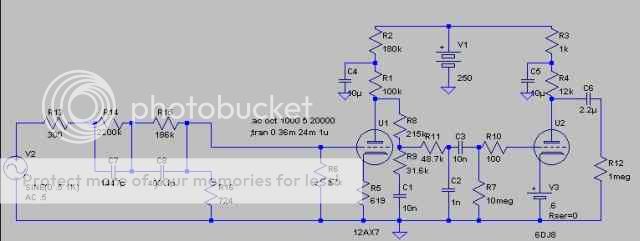
...the only change was to the ECC88's bias (I added a battery to the cathode), the model I used didn't work with grid leak. This is just for the sim, I intend to build it as designed. I used Norman Koren's tube models, as well as his inverse RIAA model. This is the response and phase shift, freq. response on top,phase on the bottom...
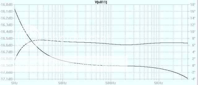
... looks good to me
That response looked bad enough to give me pause (I plan on building Thorsten's circuit soon) so I simed his circuit in LtSpice...
...the only change was to the ECC88's bias (I added a battery to the cathode), the model I used didn't work with grid leak. This is just for the sim, I intend to build it as designed. I used Norman Koren's tube models, as well as his inverse RIAA model. This is the response and phase shift, freq. response on top,phase on the bottom...
... looks good to me
- Status
- This old topic is closed. If you want to reopen this topic, contact a moderator using the "Report Post" button.
- Home
- Amplifiers
- Tubes / Valves
- Giaime's last nightmare - aka RIAA faceoff