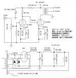
I have make a 1w power simple amp as per attached circuit.
It is direct coupled.
My problem is:
1) I find a small "dee......" sound plus hum in my speaker when there is no signal input and this sound increase with the volume control. As the voltage in the cathode of the output stage is about 60V, the original design suggest raising the heater voltage by a volatge tapping in the power circuit (i.e R6-R7). I found that if I ground the heater rather than connecting it to the 60V tapping in the power supply circuit, hum and the "dee....." sound disappear. Is it safe to directly ground the heater instead of raising it to 60V. If not, how about adding a cap across the R7.
2) In this circuit, the grid resistor in the input stage is is quite low. (i.e. 15K). Is this a reasonable value.
Thank you for your help.
Attachments
vangogh-hk said:Is it safe to directly ground the heater instead of raising it to 60V. If not, how about adding a cap across the R7.
Max. heater-cathode voltage for the 5687 is 90V. First cathode is at 0V, second at 60; you are on the safe side. Adding a cap in the lifted heater version(rated at 100V) is a good idea, IMO.
In this circuit, the grid resistor in the input stage is is quite low. (i.e. 15K). Is this a reasonable value
Yes if the pot (50k) is linear type.
Regards,
Milan
Get rid of the 15 KOhm resistor in parallel with the 50 KOhm volume control. The volume control does double duty; it also serves as the 5687 section's grid leak resistor.
Put 1 KOhm Carbon composition stopper resistors on both 5687 grids. The 5687 is QUITE vulnerable to parasitic oscillation, given its high gm.
You are using a choke I/P filter. Have you analyzed the critical current situation?
Put 1 KOhm Carbon composition stopper resistors on both 5687 grids. The 5687 is QUITE vulnerable to parasitic oscillation, given its high gm.
You are using a choke I/P filter. Have you analyzed the critical current situation?
Eli Duttman said:Get rid of the 15 KOhm resistor in parallel with the 50 KOhm volume control. The volume control does double duty; it also serves as the 5687 section's grid leak resistor.
Wouldn't you want at least a high value resistor there, in case the pot goes bad.
Sheldon
Thanks my friends
For adding a cap in the lifted heater version, what cap should I used. My 50K is an Alps volume pot.
I am using a transformer with center tap on the heater volatge output. I have connected this center tap to the voltage divider in the B+.
I have try disconnecting the 15K or use a 150K before, but the "dee...." sound level increased. I wonder if I can get rid of the noise by grounding the heater or adding a cap in the voltage divider, do I need to change the grid resistor to a higher value.
As the transformer I used gave an lower voltage than design, I use a CLCLC filter circuit to raise it output voltage
(i.e. cap input filter with 2 10H choke).
Eli Duttman said:You are using a choke I/P filter. Have you analyzed the critical current situation?
Could you please explain how to do that? Thank you in advance!
In my example: 6B4G tubes with 2 x 50/60 mA current, LCLC filtering (10H > 100uF >10H > 2x100uF per each channel)
reaction said:
Could you please explain how to do that? Thank you in advance!
In my example: 6B4G tubes with 2 x 50/60 mA current, LCLC filtering (10H > 100uF >10H > 2x100uF per each channel)
For good regulation, a minimum current needs to be drawn when choke I/P filtration is employed. The minimum is known as the Critical Current. The critical current is reached at the point where the rectifier winding and diodes begin conducting 100% of the time. A satisfactory approximation for the critical current, in mA., is given by V/L.
- Status
- This old topic is closed. If you want to reopen this topic, contact a moderator using the "Report Post" button.
- Home
- Amplifiers
- Tubes / Valves
- 5687 dc 5687 tube amp need help