If you are not certain, this may be the one. I haven't built it or heard it, but it can be configured for many different output tubes - so go ahead and wallow in indecision with no regrets. http://db.audioasylum.com/cgi/m.mpl?forum=tubediy&n=71898&highlight=300b+thorsten&r=&session=
I think it is sold as a kit by diyhifisupply.com. Maybe they sell just the transformer too.
Sheldon
I think it is sold as a kit by diyhifisupply.com. Maybe they sell just the transformer too.
Sheldon
ligascon said:About Thorsten's phono...well yes, we all should thank him (I did already) but I also thank you for having the guts to ask all the questions that I would be afraid to ask. You're the man.
Wow. I didn't think I had any "The Man"-like qualities, but apparently endless redundant, inane, elementary and redundant questions gets you in. Looks like the bar's been lowered.
The mains transformer is from diyparadiso in Belgium but I'm thinking a new one from vt4c.com
Can't seem to find a transformer with these specs on DIYParadiso.com, but I'd bet that Jack at Electra-print could wind one. Hmmm... that vt4c.com looks like an interesting site. Have you ever ordered from them?
Please note that filament supply for the d3A is supposed to be 6,3 Volts. Thorsten advices to run in at low 5,5. See, as I told you before I was afraid to ask why and just did it.
Good idea.
The common mode choke is from rs components.
Got it. Should be 7.5mH, right?
Dave-- this design looks interesting, but I think I'm gonna stay with the DRD.
If you are not certain, this may be the one. I haven't built it or heard it, but it can be configured for many different output tubes - so go ahead and wallow in indecision with no regrets. http://db.audioasylum.com/cgi/m.mpl...ten&r=&session=
Wow! That's pretty cool. Unfortunately, its probably more than I can spend given the increased number of parts. Mrs. Annan's a nice girl, but not that nice.
Any ideas on the voltage rating for the paralleled caps in the amplifier circuit? I want to make sure that I don't get underrated caps.
Also, Lundahl has the LL1623 rated at a maximum primary voltage of 270V and a primary impedance of 3K, which is different than the specs listed for this OPT on the schematic. Now, I notice that these can be wired in, like, a zillion different ways, so there must be a way to wire the 1623 to get 5.6K primary with 8R out, right?
Also, how can this be rated at 270V when we know there's 620V running through it? I know, dumb question-- but WHY is it a dumb question?
Kofi
Kofi Annan said:Wow! That's pretty cool. Unfortunately, its probably more than I can spend given the increased number of parts. Mrs. Annan's a nice girl, but not that nice.
Any ideas on the voltage rating for the paralleled caps in the amplifier circuit? I want to make sure that I don't get underrated caps.
Kofi
Actually you can do this just as you would any other version, no extra parts. Three substituted parts - an adjustable cathode resistor instead of fixed, and some different taps on the OPT's and power transformers. If you ordered them wound, the extra taps wouldn't cost much more. Might be a bit much for an early project, but as you say, it is kinda cool.
For a specific answer, it would require knowing which caps. Generally, the caps have to be rated for the voltage they will see under any circuit condition. Maybe a 20 percent safety margin beyond that is a good idea. Parallel caps require the same rating as a single caps. Caps of the same type and value can be put in series. Two caps in series split the voltage in half, but as you know from your dealings in the U.N., they may not be inclined to play nice and share equally. So you have to send in some troops in the form of a resistor divider to make sure they play nice. You can see an example of this in Thorsten's power supply as shown in the referenced thread.
Sheldon
Looks like the bar's been lowered
You dont even know...I lower it every other time, sometimes even without opening my mouth...
that vt4c.com looks like an interesting site. Have you ever ordered from them?
Yes, I ordered some tube sockets and silver wire. Really serious and no problems at all.
Should be 7.5mH, right?
Yes
Any ideas on the voltage rating for the paralleled caps in the amplifier circuit?
The Ducati Motor Run that I got are rated 450 VAC...that should give you some safety margin even if I run B+ at 650 DC Volts.
there must be a way to wire the 1623 to get 5.6K primary with 8R out, right?
Yes, it´s listed as ALT B on the factory PDF. The Lundahl part is what I used but you should feel free to try any other brand. I´m sure that either electra-print or magnequest should have suitable chokes and trannies...it´s your call.
Good luck with all the preparations. Take care,
Luis
Thats primary signal voltage, VAC RMS.
Thanks!
Actually you can do this just as you would any other version, no extra parts. Three substituted parts - an adjustable cathode resistor instead of fixed, and some different taps on the OPT's and power transformers. If you ordered them wound, the extra taps wouldn't cost much more. Might be a bit much for an early project, but as you say, it is kinda cool.
Yep. Kinda cool, but might be too much for me on this go 'round.
The Ducati Motor Run that I got are rated 450 VAC...that should give you some safety margin even if I run B+ at 650 DC Volts.
OK-- this is confusing to me since I thought that I would need to multiply the 450VAC x 1.414 to get a total DC voltage rating of ~636V, which would not accommodate the 650VDC. I have found some 420VAC rated motor run caps that I would have like to have used in the PSU, but my calculations indicate that this would only be ~593VDC-rated and would not work.
Of course, nothing in the universe have proven more consistently wrong than my calculations, so are the motor run caps rated conservatively or am I not calculating this right?
Yes, it´s listed as ALT B on the factory PDF. The Lundahl part is what I used but you should feel free to try any other brand. I´m sure that either electra-print or magnequest should have suitable chokes and trannies...it´s your call.
I figured that one out after I posted... thanks!
I'll probably stick with the Lundahl OPT, but I may mix it up a bit with the PSU and chokes.
Also, did you use motor run caps in the amp circuit, the PSU or both?
Yours in ignorance,
Kofi
Kofi Annan said:so are the motor run caps rated conservatively or am I not calculating this right?
Kofi [/B]
Yes, generally so. They are designed for pretty severe AC duty, so the AC ratings reflect that. example: http://www.cornell-dubilier.com/misc/hot.htm
Sheldon
Thanks!
Even more questions:
So, does that mean I could safely use a 370VAC-rated motor run capacitor for the power supply?
Also, can you(ze) tell me how many mA I the circuit consumes or what would be the recommended mA rating for a power transformer? I may be having one wound and I know that this question will come up.
Kofi
Kofi Annan said:Thanks!
...
So, does that mean I could safely use a 370VAC-rated motor run capacitor for the power supply?
...
Kofi
If you wish to be conservative multiply your AC rating by 1.4 to get the DC rating. In this case 518 VDC. And that is working voltage. They can take higher voltages for short periods of time (as when charging up).
I've had motor run (and make sure they are motor run not motor start) caps in my SE KT88 monoblocks for about a year now. The PS voltage is 425, max voltage on the caps as the PS stabilizes over the first 30 seconds or so is 560. I think the caps work great.
Having said all that I've been told I can safely double the AC rating for DC use but I'm too much of a coward... er, uh, I mean conservative, yeah, that's it; conservative, with electricity to try that (so far).
Kofi Annan said:Thanks!
Even more questions:
So, does that mean I could safely use a 370VAC-rated motor run capacitor for the power supply?
Also, can you(ze) tell me how many mA I the circuit consumes or what would be the recommended mA rating for a power transformer? I may be having one wound and I know that this question will come up.
Kofi
Quite likely on the 370 caps. But if you're worried about it use 440AC caps. It's a very common motor run value.
How many ma? Depends on the circuit, but no higher math required here. Just add up all the current sinks - bias for each tube and any bleeder resistors, etc.. If you are not sure of the transformer quality, overrate by 20%. If you have one wound, just give the winder your circuit.
Sheldon
How many ma?
150mA is usually more than enough. With most 300b's drawing around 70mA and the driver say 8mA-45mA ..plus maybe a little by a bleeder here or there.
So anything from 150mA to 400mA is fine. For your HT/B+. (Mono)
The filaments per monoblock. Say 2,5-0-2,5V/3A for the rectifier tube.
5V/2A for the 300B perhaps an extra 2.5V/2A tap so that you could add to the 5V tap in case you want to upgrade or try something like Guido Tent's heaters. (You need a little voltage headroom for the circuitry)
3,15-0-3,15/2A or whatever your driver tube requires. Et voila! 0 goes to elevated bias for minimal noise.
And as Lynn Olsen always says..try to get an electrostatic screen between primary and secondary. It only adds a couple of dollars but you prevent unneccesary noise right from the word go. Almost a free lunch so to speak.
Having said all that I've been told I can safely double the AC rating for DC use but I'm too much of a coward... er, uh, I mean conservative, yeah, that's it; conservative, with electricity to try that (so far).
I'd be a bit scared too. I think I'll look for a 440VAC.
So anything from 150mA to 400mA is fine. For your HT/B+. (Mono)
Thanks!
Now I have some power supply questions:
Attached is the PSU that Luis uses and I think its neato, so I'd like to implement it. What my dim brain has noticed is that somehow, he's using a 250V secondary to get 620VDC out. I'm thinking that this means maybe the diodes at the plates of the 274A rectifier are acting as a voltage doubler and the bootstrapping (is this the right term?) of the 5.5V supply is helping increase the voltage as well.
It could just as easily be pixie dust, though.
Also, I know that the 274A is one hell of a rectifier, but its also got one hell of a price tag. Could I use another rectifier here without much modification to the PSU circuit?
Also, anyone ordered parts from Jac Music before? They have a pair of TJ "Full Music" 274As that aren't go-knock-over-a-liquor-store expensive (about $150US), so they may be the ticket.
Kofi
Attachments
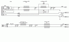
Kofi Annan said:Attached is the PSU that Luis uses and I think its neato, so I'd like to implement it. What my dim brain has noticed is that somehow, he's using a 250V secondary to get 620VDC out. I'm thinking that this means maybe the diodes at the plates of the 274A rectifier are acting as a voltage doubler and the bootstrapping (is this the right term?) of the 5.5V supply is helping increase the voltage as well.
Also, I know that the 274A is one hell of a rectifier, but its also got one hell of a price tag. Could I use another rectifier here without much modification to the PSU circuit?
Kofi
That transformer is mislabled. It's actually a 250-0-250 center tapped transformer. But the center tap is unused, so the sections are in series, giving a 500v secondary. Since it's used that way, it should be labeled 500V.
I think that the 274b is the same internally as the 274a (confirm that with the experts here). If so, the 274b might be the better choice, since I believe its pin configuration and socket (octal) makes it easier to sub in other rectifiers. The 274b has a higher internal resistance than most of the substitutes, so you would get higher B+ by changing to something different. Also, some of the other tubes will tolerate a larger input cap. The best way to look at this is just plug that circuit into PSUD and play. You can't model the hybrid rectifier directly, but you can model a SS bridge and a tube bridge and split the difference in output voltage.
Sheldon
That transformer is mislabled. It's actually a 250-0-250 center tapped transformer. But the center tap is unused, so the sections are in series, giving a 500v secondary. Since it's used that way, it should be labeled 500V.
Wow! Thanks! I coulda made a bad mistake there.
So are the secondaries really 5V and 5.5V respectively? These seem like odd values. If they are, that's fine-- I can have one wound, but I'd just like to know.
I think that the 274b is the same internally as the 274a (confirm that with the experts here). If so, the 274b might be the better choice, since I believe its pin configuration and socket (octal) makes it easier to sub in other rectifiers. The 274b has a higher internal resistance than most of the substitutes, so you would get higher B+ by changing to something different. Also, some of the other tubes will tolerate a larger input cap. The best way to look at this is just plug that circuit into PSUD and play. You can't model the hybrid rectifier directly, but you can model a SS bridge and a tube bridge and split the difference in output voltage.
Good news! I'll wait for the verdict from the experts, but I might just go ahead and do the 274A anyway. I always cut corners on these projects and just once I might build to spec...
Also, how about these for PSU motor run caps. Will they be OK?
Kofi
Also, anyone ordered parts from Jac Music before?
I have. Jac is a nice guy, he has a love for tubes and prices are fair.
Recommended.
I have. Jac is a nice guy, he has a love for tubes and prices are fair.
Thanks!
Now about those motor run caps...
Looks like a good deal, 440VAC motor run caps are more than up to it.
Alright!
If using tube rectification and capacitor input, check tube ratings, you may want to use a smaller cap for the first section or series resistance.
The PSU has a 4uF cap in the first section, which I believe is appropriate for the 274A rectifier.
OK-- in the interest of understanding this design, I have noticed that the plate is putting out 60mA (quiescent current, I guess) at 599V, but that seems like waaaay too much voltage. I have been trying to plot the loadline and for a 5.6K primary and a 60mA Ic, we should be at about 336V, but we're not.
So the question is, how dumb is my next question, which is how can we have almost 600V at the plate of the 300b?
I know I'm gonna get slapped for this one and I'm gonna deserve it too, but I gotta know.
Kofi
Kofi Annan said:
OK-- in the interest of understanding this design, I have noticed that the plate is putting out 60mA (quiescent current, I guess) at 599V, but that seems like waaaay too much voltage. I have been trying to plot the loadline and for a 5.6K primary and a 60mA Ic, we should be at about 336V, but we're not.
Kofi
Actually you are at about 336V. The question when talking about voltage is; voltage with respect to what? Voltage is the potential between two points. When we are talking about plate voltage, we are talking about the voltage between the plate and the cathode. Your cathode is at 249V above "ground". Your plate is at 599V above ground. So your plate voltage is 599V minus 249V, or 350V.
Sheldon
- Status
- This old topic is closed. If you want to reopen this topic, contact a moderator using the "Report Post" button.
- Home
- Amplifiers
- Tubes / Valves
- Kofi Annan in: "300beee!" or "Kofi Gets a Toy"