Howdy folks,
Well I've run into my first snag with my DIY amp-the bias network.
Basically I'm tapping the HV secondary for bias. Set up:
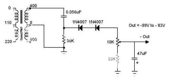
HV secondary in series with .05uf 600v Sprague Orange Drop cap. Next a diode (1000 PIV, 4 amp) in series with the cap, going to a trimpot. The junction of the cap and diode has a 27k 1 watt resistor going to ground.
Last week the .05 caps shorted and took out the 27k resistors in the process. Replaced the caps and resistors, but still having very erratic behavior with the bias.
Someone told me the Orange Drops were the issue, so I bought some PIO caps from Angela, but then I got to thinking:
Shouldn't the diode's PIV rating be 2.8 times the voltage of the secondary? I read elswhere a good rule of thumb is to make sure the PIV is 3 times the secondary voltage.
I'm thinking maybe the problem has been the diodes all along, so I'm putting in some 1,500v PIV diodes tonight and seeing if that fixes the problem.
Anybody got any insight into this diode situation?
Thanks for any and all help,
mr mojo
Well I've run into my first snag with my DIY amp-the bias network.
Basically I'm tapping the HV secondary for bias. Set up:
HV secondary in series with .05uf 600v Sprague Orange Drop cap. Next a diode (1000 PIV, 4 amp) in series with the cap, going to a trimpot. The junction of the cap and diode has a 27k 1 watt resistor going to ground.
Last week the .05 caps shorted and took out the 27k resistors in the process. Replaced the caps and resistors, but still having very erratic behavior with the bias.
Someone told me the Orange Drops were the issue, so I bought some PIO caps from Angela, but then I got to thinking:
Shouldn't the diode's PIV rating be 2.8 times the voltage of the secondary? I read elswhere a good rule of thumb is to make sure the PIV is 3 times the secondary voltage.
I'm thinking maybe the problem has been the diodes all along, so I'm putting in some 1,500v PIV diodes tonight and seeing if that fixes the problem.
Anybody got any insight into this diode situation?
Thanks for any and all help,
mr mojo
Hey poobah,
Having some server issues at work so I'm having trouble posting images, but if you check the post at the top of this link there's a working link to the schematic:
http://www.diyaudio.com/forums/showthread.php?threadid=63431
800VCT, so I've got 400V on each half of the secondary.
Best,
mr mojo
Having some server issues at work so I'm having trouble posting images, but if you check the post at the top of this link there's a working link to the schematic:
http://www.diyaudio.com/forums/showthread.php?threadid=63431
800VCT, so I've got 400V on each half of the secondary.
Best,
mr mojo
Hmmm,
You're talking about C25 & C26???
All I can think is that the voltage is just too much for the caps. 400 volts RMS means 566 Volts... if you are running right on high line voltage (125) instead of 117 you could wind up with 604 Volts. That should be right on the hairy edge but what if a spike came along? (they did both fail at the time did they not?)
You know usually there is good safety margin but these caps are seeing alot of AC current which heats 'em up, and eats the safety margin...
I wouldn't spend any money on boutique caps... the orange drops with a 1000 Volt rating would be better... the diodes in the circuit shoud have at least 800-1000 Volt. the diodes. You can put 2 diodes in series to jack up their PIV rating.
Why did 600 Volt papers work and not these... the papers weren't dealing with the nasty recovery of a jelly bean silicon diode maybe. I think all this is just TOO close to the limits.
mr mojo said:800VCT, so I've got 400V on each half of the secondary.
Not so, I'm afraid. Assume that the transformer charges the reservoir capacitor to its peak voltage of 400V x root 2 = 565V. Now the polarity at the end of the transformer/diode changes and it's at -565V. Your diode now has 1130V across it.
poobah,
I really appreciate the help! Like I've said before, I'm not an engineer and the more I learn the more I realize how much I don't know!
I'm replacing the diodes with 1500PIV 1 amps as well as 630v PIO caps. The caps are temporary until I can order some 1600v Orange Drops when Antique re-opens.
Tom,
I think you and I are on the same page, your suggestion is just about exactly what I'm in the process of doing. Guess this is just part of the learning curve for me and part of the testing and evaluation of what's basically a prototype amp-even if the circuit was designed by the engineers as Westinghouse, it's not as if this is a widely built circuit with a lot of documentation from actual use!
EC8010,
Spot on-that's exactly what I'm doing. When I started researching diode ratings I came across the 1.6 FV and the 2.8 PIV rating and suddenly I beleived I had my answer-but like I said above I'm still scaling the learning curve so it's nice to have someone more knowledeable backing up my reasoning.
Thanks so much for you help folks-I really do appreciate it so much. This forum is the BEST!! I'll update this thread next week after my repairs. I'm also replacing the HV filter caps with 450v Spragues in series with voltage dividers so I'll post some pics of that whole affair as well.
Hope you all have a merry Christmas and a happy and safe new year!
Best,
mr mojo
wouldn't 2 diodes in series work to increase the PIV?
i was also experimenting with my 410-0-410 tranny for my fixed bias experiments. i use the same 600V Orange Drops you used but a friend adviced me to use a 0.1 to squeeze the necessary negative voltage for my opt tube grids since 0.05 yields too low negative voltage. but unlike your schematic mine supplies both the left and right channel. maybe I should separate them like in the schematics (one set for every channel).
would something like this work in place of 1500V diodes?
Couldn't the rating issue be solved also by making a capacitive voltage divider. How about two caps in series, connecting the diode between them? It would be cheaper in this case just to use two diodes. But if diode noise were an issue the cap divider could be used to get to reasonable Schottky options, no?
Sheldon
Sheldon
I used a similar bias circuit in my 45 SE amplifier which you can find on my website.
I had a LOT of problems with the capacitors, and it was not the voltage rating that was the problem - it was the ripple current flowing through them. I ended up using four 1KV 0.1uF in series parallel to get enough current capability for them to survive. I also added a series resistor as well to limit the current through the capacitors to something sane, line transients will kill them instantly if you don't.
Take a look at what I wrote about this issue here: http://www.kta-hifi.net/projects/amp_page/45dht/45_dht.html
look at the update section under other comments, you want the one dated 9.13.98
Once the problem was solved it has stayed solved, but IMHO this is probably not the most reliable approach to deriving bias for your amplifier..
One other thought is that metalized mylar film caps don't seem to survive due to heating in the metalized mylar, the ones I use for this circuit are all surplus film and foil type and they have survived more than seven years of use.
edited:
was duplicate post to post 14 , edited with some new thoughts
edited:
was duplicate post to post 14 , edited with some new thoughts
kevin,
I appreciate your insights-I was thinking the under-rated diodes were only part of the problem as well.
I think part of the issue is that the ratings listed for the Orange Drops is usually VDC. IIRC, the 1600 VDC rated Orange Drops are rated for 6 or 800 VAC. Do you think that would cure it?
Also: What exactly are these caps doing that a 50 watt wire-wound power resistor couldn't do?
If not, a final solution I'm contemplating is a small transformer just for a dedicated bias supply: something @100 vct, 150 ma. That would cure it for sure...
Best,
mr mojo
If you want capacitors for taking abuse, try snubber capacitors. Cornell Dubilier 942Cs are good for high current applications. Self healing axial film capacitors of hybrid section design using polypropylene film, metal foils and metallized polypropylene dielectric.
942C16P1K .1uF, 1600VDC, 3425 dV/uS, 342 amp peak, 11.4 amp rms. Typical ESR is cited as 4 milliohm, and ESL as 24nH.
Its not AC dissipation or corona issues thats killing these capacitors, its current.
942C16P1K .1uF, 1600VDC, 3425 dV/uS, 342 amp peak, 11.4 amp rms. Typical ESR is cited as 4 milliohm, and ESL as 24nH.
Its not AC dissipation or corona issues thats killing these capacitors, its current.
kevinkr said:I Once the problem was solved it has stayed solved, but IMHO this is probably not the most reliable approach to deriving bias for your amplifier..
Are the caps required? For a bias supply with little current, coudn't one just run a diode to one rail for a single wave rectifier and use RCRC, etc., for smoothing and voltage reduction?
Sheldon
Mojo,
It is the AC current and therefore the AC voltage rating on the cap that bit you one this one. 715P's with the 600-800 AC votage rating should do just fine here. There is a 715P HV cap that would be best, but I bet you cant find 'em (in 2's at least).
We could go through a whole calculation of the AC current and figure out power from dissipation tangent... lot o work ... just use a good cap with an ac rating.
I'll bet the old caps were physically warm to the touch when running... we are taught that caps don't dissipate power... WRONG. Be carfeull is you touch them... don't touch the metal part...
This is not bad circuit... just a tricky one. We usually use caps for DC blocking (AC coupling) or DC smoothing. So when we get to an application where we use a cap to actually move real energy from point to point... we all get thrown off for a minute.
Mojo, what type of Orange Drop was there in the first place?
The AC voltage rating is largely determined by corona resistance rather than current handling. The 942Cs will handle far more current than the 715Ps though thier VAC rating is lower. The reason the 942Cs will handle more current is thier hybrid metallized/foil construction vs straight metallized. That said, I have little experience with the 715Ps.
The 942Cs are very conservatively rated, Ive seen them used with VAC peak= VDC rating just fine.
Just to be sure Im clear, when I spoke of AC dissipation I was referring to dielectric absorption issues and not any I2R.
The 942Cs are very conservatively rated, Ive seen them used with VAC peak= VDC rating just fine.
Just to be sure Im clear, when I spoke of AC dissipation I was referring to dielectric absorption issues and not any I2R.
- Status
- This old topic is closed. If you want to reopen this topic, contact a moderator using the "Report Post" button.
- Home
- Amplifiers
- Tubes / Valves
- Question about PIV rating of diodes...