My math says the gain of the "classic" RCA phono circuit is 45 dB. That's not far off the "magic" 50 dB. that raises MM carts. to CDP level.
I have some thoughts on squeezing the extra 5 dB. out and I'd appreciate feedback.
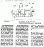
Make the B+ rail 300 V. CCS load (1 mA.) the 1st gain block and use the same Agilent LED as employed in the Bottlehead Seduction for bias. Increase the 2nd gain block's load resistance to 120 KOhms. Buffer the 2nd gain block's O/P with a DC coupled Zetex TO92 case MOSFET, as described in MOSFET "Follies".
MOSFET "Follies"
Bass extension will be improved by switching the 2nd gain block to contact (grid leak) bias. The cathode will be grounded and a 20 MOhm Caddock resistor replaces RCA's 680 KOhm value in the grid leak position.
I have some thoughts on squeezing the extra 5 dB. out and I'd appreciate feedback.
Make the B+ rail 300 V. CCS load (1 mA.) the 1st gain block and use the same Agilent LED as employed in the Bottlehead Seduction for bias. Increase the 2nd gain block's load resistance to 120 KOhms. Buffer the 2nd gain block's O/P with a DC coupled Zetex TO92 case MOSFET, as described in MOSFET "Follies".
MOSFET "Follies"
Bass extension will be improved by switching the 2nd gain block to contact (grid leak) bias. The cathode will be grounded and a 20 MOhm Caddock resistor replaces RCA's 680 KOhm value in the grid leak position.
Attachments
This was my first phono amp project. I never could get the bass quite right,maybe 45db explains it. I hope you get it to run properly. I might try it again.
the article claims that miller effect doesn't affect the follower, i did a simple simulation with the a voltage source with 35k output impedance and a mosfet with 360pf gate capacitance. i get quite abit of roll off even at 1khz.
am i missing something?
am i missing something?
hacknet said:the article claims that miller effect doesn't affect the follower, i did a simple simulation with the a voltage source with 35k output impedance and a mosfet with 360pf gate capacitance. i get quite abit of roll off even at 1khz.
am i missing something?
Look here. Mike Preamp Thread Cogsncogs made the KEY point. While the source does follow the gate, transfer capacitance interacts adversely with a high Rp tube to roll HF off.
The capacitances of TO220 case FETs are large. OTOH, the capacitances of the little TO92 case Zetex FET are much more reasonable and have a smaller impact.
If push comes to shove, a cap. coupled JFET as the buffer will get the job done. However, I'd like to be DC coupled at the FET's gate.
Someone more clever than I am and really knowlegeable about RIAA EQ might rework the network to take advantage of HF roll off when the transfer capacitance is "high".
hmm.. yeah. i can't find a source for the zetex mosfets. i think i might do the jfet approach. i'll look around and see..
is there any software out there that can do distortion analysis?
is there any software out there that can do distortion analysis?
In the MOSFET Follies link the author says: >>"But wait!" I hear you yell. "The MOSFET has a big gate-source capacitance. Won't that suck all the high frequencies out of the signal?" No, it won't. The big gate-source capacitor is there, OK, but when the device is hooked up as a follower, the apparent capacitance seen by a circuit driving the MOSFET gate is reduced to a very small level by the fact that the source is following the gate almost perfectly, so the apparent capacitance is reduced by the local feedback to an inconsequential level. Even a high impedance 12AX7 plate is not affected in the audio range by this capacitance. Even the big power, big capacitance MOSFETs do this one OK. I have done this, and what's more, done the necessary measurements to find the effect on the response of the composite stage - and there is no detectable change in frequency response below 30kHz. None.<<
Yeah, but… There WILL be phase shift in the audio band due to this capacitance even if here is “no detectable change in the frequency response below 30KHz” It's not just the absolute value of the FET's capacitance that we need to consider, it's also the nasty variability of that capacitance with signal swing. Even if the absolute value has little effect on frequency response (magnitude) at 30 KHz, there will be in-band phase shift due to this capacitance this is modulated with signal swing, even with the bootstrapping effect of a follower. The worst way to drive such a capacitance is with a high Z source, say a 12AX7 plate. The result will be phase intermodulation distortion, the worst kind. This is the prime reason why tubes sound better than transistors, IMO. A little bit of PIM adds a false edge to music that some might find appealing on first listen. IMO, it’s best to avoid this approach.
Yeah, but… There WILL be phase shift in the audio band due to this capacitance even if here is “no detectable change in the frequency response below 30KHz” It's not just the absolute value of the FET's capacitance that we need to consider, it's also the nasty variability of that capacitance with signal swing. Even if the absolute value has little effect on frequency response (magnitude) at 30 KHz, there will be in-band phase shift due to this capacitance this is modulated with signal swing, even with the bootstrapping effect of a follower. The worst way to drive such a capacitance is with a high Z source, say a 12AX7 plate. The result will be phase intermodulation distortion, the worst kind. This is the prime reason why tubes sound better than transistors, IMO. A little bit of PIM adds a false edge to music that some might find appealing on first listen. IMO, it’s best to avoid this approach.
Brian,
You make a good point. A low gate capacitance JFET cap. coupled to the anode of the 'X7 will work fine as the buffer, but I'd like to salvage the DC coupled gate.
OK, make the 2nd gain block a 12AT7 section. CCS load the 'T7 at 3 mA. CCS loading maximizes both gain and linearity. Gain should be about 35 dB. Given its high gm and low Rp, the 'T7 is better suited to driving the little Zetex MOSFET than the 'X7 is.
Konnichiwa,
Just a small note, 50db is too much gain.
Here is why.
The CD has a full scale output level at 2V. The average level is usually 14db lower or 400mV.
LP is defined with 5cm/S as 0db but allows per IEC 25cm/S level, in other words a 14db headroom. So, a Phonostage to match CD needs to produce 400mV with a nominal input of 5cm/S, thyphically MM level is reckoned to be 2.5mV...10mV with a "design center" at 5mV for 5cm/S.
So, 5mV need to produce 400mV or 38db gain. It is desirable to have 6db more gain (possibly switchable?) than that which places our nominal input at 5mV for 5cm/S and at least 12db headroom on top of the 14db headroom designed into LP for that nominal input.
So we need 26db headroom on 2.5mV input voltage and 44db Gain for a "bogey" MM Phonostage unless really quiet Grado's are used. Output referred we hence need the ability to produce 8V RMS with low distortion with 44db Gain. Better would be a Phonostage with a selectable MM gain at 32db, 38db and 44db.
Then adding a Transformer with a 1:5/10/20 option makes sure we can accomodate a wide range of MC Pickups as well, with 1:5 giving nominal 0.5mV input with 0.25mV and 0.125mV @ 5cm/S as nominal input for 44db gain selected.
Sayonara
Eli Duttman said:My math says the gain of the "classic" RCA phono circuit is 45 dB. That's not far off the "magic" 50 dB. that raises MM carts. to CDP level.
Just a small note, 50db is too much gain.
Here is why.
The CD has a full scale output level at 2V. The average level is usually 14db lower or 400mV.
LP is defined with 5cm/S as 0db but allows per IEC 25cm/S level, in other words a 14db headroom. So, a Phonostage to match CD needs to produce 400mV with a nominal input of 5cm/S, thyphically MM level is reckoned to be 2.5mV...10mV with a "design center" at 5mV for 5cm/S.
So, 5mV need to produce 400mV or 38db gain. It is desirable to have 6db more gain (possibly switchable?) than that which places our nominal input at 5mV for 5cm/S and at least 12db headroom on top of the 14db headroom designed into LP for that nominal input.
So we need 26db headroom on 2.5mV input voltage and 44db Gain for a "bogey" MM Phonostage unless really quiet Grado's are used. Output referred we hence need the ability to produce 8V RMS with low distortion with 44db Gain. Better would be a Phonostage with a selectable MM gain at 32db, 38db and 44db.
Then adding a Transformer with a 1:5/10/20 option makes sure we can accomodate a wide range of MC Pickups as well, with 1:5 giving nominal 0.5mV input with 0.25mV and 0.125mV @ 5cm/S as nominal input for 44db gain selected.
Sayonara
Thorsten,
Thanks for your remarks.
After the losses in the EQ network, the net gain of a CCS loaded 'X7 section will be < 20 dB. Let's say the gain is 18 dB., for purposes of discussion. That leaves 26 dB. for the 2nd triode to produce. To drive the Zetex MOSFET buffer, a high gm/low Rp type is indicated. The gain of a CSS loaded 6922 is approx. 30 dB. That's 4 dB. too much, but for several reasons the 6922 just might be best, in spite of its "high" gain. I don't know if the mu 22 ECC99 is quiet enough and if it will work well with contact bias.
This is getting really interesting. 🙂 A NOS TFK ECC808 could provide the 1st gain block for both channels and a JJ E88CC could provide the 2nd gain block for both channels. The internal shields of both types should help channel separation a little.
Brian Beck said:In the MOSFET Follies link the author says: >>"But wait!" I hear you yell. "The MOSFET has a big gate-source capacitance. Won't that suck all the high frequencies out of the signal?" No, it won't. The big gate-source capacitor is there, OK, but when the device is hooked up as a follower, the apparent capacitance seen by a circuit driving the MOSFET gate is reduced to a very small level by the fact that the source is following the gate almost perfectly, so the apparent capacitance is reduced by the local feedback to an inconsequential level.
This is true, however the gate-drain capacitance is not reduced, Cgd of the zetex MOSFET is 4pF, the common IRF820 is about 30pF.
Konnichiwa,
Let us assume we get an ECC83 with an Ra of 80K (low voltage, low current operation like I use) and an unbypassed cathode resistor of 620 Ohm we end up with an effective anode impedance in the 140K region.
If we do not use an anode resistor of 100K but a ccs this impedance is quite variable between valves, but using an anode resistor and unbypassed cathode resistor stabilises the effective output impedance quite well at around 60K. In this case the gain at the anode will be around 40. As we have actually the load of the RIAA also in the anode circuit we have actually at the loaded anode our gain is around 37.5.
The 60K will become part of the RIAA though. In my case you have a 215 series resistor which with around 60K Source impedance becomes 275K. Add the 31K6 series resistor and the impedance of the 10nF capacitor @ 1KHz which is around 15K and we have 275K : 48K voltage divider or 6.73 attenuation, by which the gain of 37.5 is divided.
This leaves us after the RIAA EQ in my example with a gain of 5.6 or 15db.
The traditional Resistor loaded ECC88 has in my use (high current, low voltage - 90V/12mA, 12K) a gain of around 26 or 28db, an effective anode impedance of around 3K and thus an output impedance around 2k4 which is not exactly spectaculary low, but tollerable.
So, in total we get in theory 43db gain for my ECC83/ECC88 Phonostage with some variability mainly from the ECC88 and moderate outpuit impedance.
And that is largely my thinking behind my circuit, I changed the RIAA EQ as I did because this circuit allows the independent adjustment of all three timeconstants to a larger degree and easier than the traditional RIAA Circuits, this and the second stage gridleak bias being the others.
In the end the original RCA Phonostage is barely recognisable, however that was my own line of optimisation of the RCA Circuit:
1) Fix the output stage high output impedance (ECC88 @ loads of current).
2) Fit a more accurate and adjustable RIAA (semi-split RIAA).
3) Stabilise the input stage gain and output impedance (unbypass input stage cathode R).
4) Readjust the interstage coupling capacitor position and eliminate the output stage cathode RC.
I hope my reasoning and approach will help you in your quest.
I am not really against Mosfet buffers BTW, or anything else that makes things to work well. I just like simplicity a lot, so I tend towards the simplest solution that delivers the results that I need.
Sayonara
PS, for others (Eli knows) here "my" circuit discussed:
http://www.diyaudio.com/forums/showthread.php?postid=335624#post335624
Eli Duttman said:Thanks for your remarks.
After the losses in the EQ network, the net gain of a CCS loaded 'X7 section will be < 20 dB.
Let us assume we get an ECC83 with an Ra of 80K (low voltage, low current operation like I use) and an unbypassed cathode resistor of 620 Ohm we end up with an effective anode impedance in the 140K region.
If we do not use an anode resistor of 100K but a ccs this impedance is quite variable between valves, but using an anode resistor and unbypassed cathode resistor stabilises the effective output impedance quite well at around 60K. In this case the gain at the anode will be around 40. As we have actually the load of the RIAA also in the anode circuit we have actually at the loaded anode our gain is around 37.5.
The 60K will become part of the RIAA though. In my case you have a 215 series resistor which with around 60K Source impedance becomes 275K. Add the 31K6 series resistor and the impedance of the 10nF capacitor @ 1KHz which is around 15K and we have 275K : 48K voltage divider or 6.73 attenuation, by which the gain of 37.5 is divided.
This leaves us after the RIAA EQ in my example with a gain of 5.6 or 15db.
The traditional Resistor loaded ECC88 has in my use (high current, low voltage - 90V/12mA, 12K) a gain of around 26 or 28db, an effective anode impedance of around 3K and thus an output impedance around 2k4 which is not exactly spectaculary low, but tollerable.
So, in total we get in theory 43db gain for my ECC83/ECC88 Phonostage with some variability mainly from the ECC88 and moderate outpuit impedance.
And that is largely my thinking behind my circuit, I changed the RIAA EQ as I did because this circuit allows the independent adjustment of all three timeconstants to a larger degree and easier than the traditional RIAA Circuits, this and the second stage gridleak bias being the others.
In the end the original RCA Phonostage is barely recognisable, however that was my own line of optimisation of the RCA Circuit:
1) Fix the output stage high output impedance (ECC88 @ loads of current).
2) Fit a more accurate and adjustable RIAA (semi-split RIAA).
3) Stabilise the input stage gain and output impedance (unbypass input stage cathode R).
4) Readjust the interstage coupling capacitor position and eliminate the output stage cathode RC.
I hope my reasoning and approach will help you in your quest.
I am not really against Mosfet buffers BTW, or anything else that makes things to work well. I just like simplicity a lot, so I tend towards the simplest solution that delivers the results that I need.
Sayonara
PS, for others (Eli knows) here "my" circuit discussed:
http://www.diyaudio.com/forums/showthread.php?postid=335624#post335624
Konnichiwa,
Ib? Do you mean Ia?
The Anodic current is around 0.5mA, in both stages.
As operated Mu is around 90 and Ra is a little over 100K, so stage-gain without accounting for the RIAA Network is around 45.
Sayonara
PS, when driving the RIAA directly of the Anode consider NOT using a CCS and NOT using a bypassed cathode resistor (or similar). You do not loose as much gain as you think and linearity is fine.
If you intend to add a Mosfet Buffer between first gainblock and RIAA by all means use CCS loading and LED bias, it is actually apropriate in that case.
Eli Duttman said:Let's go back to RCA's original schematic. What's Ib for the 1st gain block?
Ib? Do you mean Ia?
The Anodic current is around 0.5mA, in both stages.
As operated Mu is around 90 and Ra is a little over 100K, so stage-gain without accounting for the RIAA Network is around 45.
Sayonara
PS, when driving the RIAA directly of the Anode consider NOT using a CCS and NOT using a bypassed cathode resistor (or similar). You do not loose as much gain as you think and linearity is fine.
If you intend to add a Mosfet Buffer between first gainblock and RIAA by all means use CCS loading and LED bias, it is actually apropriate in that case.
hey, this has got me interested again.
does the output impedance of the output stage play a part in the riaa filter?
i think it does right? so if i use a mosfet buffer, i would have to re calculate the values because the mosfet buffer has a much lower output impedance?
would it make sense to use a ccs on the plate if i use a mosfet buffer? i was hoping to do so but was adviced against it a long time back because of a change in output impedance. i was hoping to get more gain and linearity with the ccs.
i'm getting excited! thanks a million in advance!
Konnichiwa,
Of course.
Yes, you need to re-do the RIAA EQ.
Maybe, it would require a very low capacitance FET though, as the ECC83/12AX7 will have around 100K Anode impedance, 30pF load capacitance would make for a 3db rolloff at 50KHz, so a lot less than that would be desirable.
The scheme I use with an unbypassed cathode resistor is as linear, if not better, more gain you will get, but what for, the noise levels don't allow for much less than 5mV as "0db" input anyway.... Also, with 100K Anode impedance you need a very high impedance CCS (> 100MOhm) to avoid nonlinear interaction as well.
Sayonara
hacknet said:does the output impedance of the output stage play a part in the riaa filter?
Of course.
hacknet said:so if i use a mosfet buffer, i would have to re calculate the values because the mosfet buffer has a much lower output impedance?
Yes, you need to re-do the RIAA EQ.
hacknet said:would it make sense to use a ccs on the plate if i use a mosfet buffer?
Maybe, it would require a very low capacitance FET though, as the ECC83/12AX7 will have around 100K Anode impedance, 30pF load capacitance would make for a 3db rolloff at 50KHz, so a lot less than that would be desirable.
hacknet said:i was hoping to do so but was adviced against it a long time back because of a change in output impedance. i was hoping to get more gain and linearity with the ccs.
The scheme I use with an unbypassed cathode resistor is as linear, if not better, more gain you will get, but what for, the noise levels don't allow for much less than 5mV as "0db" input anyway.... Also, with 100K Anode impedance you need a very high impedance CCS (> 100MOhm) to avoid nonlinear interaction as well.
Sayonara
Maybe, it would require a very low capacitance FET though, as the ECC83/12AX7 will have around 100K Anode impedance, 30pF load capacitance would make for a 3db rolloff at 50KHz, so a lot less than that would be desirable.
Thorsten,
The little TO92 case MOSFET from Zetex "shines", as its gate capacitance is about 4 pF. That should be negligible if a 6922 section is driving it and acceptable if a 12AX7 section is driving it. The gate capacitance of TO220 case MOSFETs is 30+ pF. That's NOT good for use with 'X7s.
i was thinking of an anode ccs with 2 transistors say a mpsa92 and a mje350 with an led as vref? is it any better than a cathode source?
kONNICHIWA,
Yup, so using this you are limited to 0.7W dissipation, which in turn, after suitable derating and all the rest, when using the standard RCA Circuit with 250V +B makes for in theory 14mA and in practice derated around 5mA.
This is still rather marginal in my books but seems to work for ICL in japan:
Sayonara
Eli Duttman said:The little TO92 case MOSFET from Zetex "shines", as its gate capacitance is about 4 pF. That should be negligible if a 6922 section is driving it and acceptable if a 12AX7 section is driving it. The gate capacitance of TO220 case MOSFETs is 30+ pF. That's NOT good for use with 'X7s.
Yup, so using this you are limited to 0.7W dissipation, which in turn, after suitable derating and all the rest, when using the standard RCA Circuit with 250V +B makes for in theory 14mA and in practice derated around 5mA.
This is still rather marginal in my books but seems to work for ICL in japan:
An externally hosted image should be here but it was not working when we last tested it.
Sayonara
Konnichiwa,
If you are talking about the C4S, this has around 5M Impedance, which is okayish, but not great.
I suspect that, excepting the lower gain, a stage with unbyassed cathode resistor and anode load resistor will perform better with an ECC83, omiting any solid state CCS, buffers and all that Jazz, which merely adds complexity without actually providing any real performance enhancements, except an extra 6 - 8db gain, which may or may not be desirable or required.
The ECC88/6DJ8 is more ameanable to CCS loading as it's anode impedance is by a factor 30 lower and it is a more linear device, so the same CCS as used for the ECC83 would have 1/30th of the impact on sound.
This is the usual tradeoff, you need a whole lot of extra complexity to gain very small improvements and may end up with disimprovements along the way.
Sayonara
hacknet said:i was thinking of an anode ccs with 2 transistors say a mpsa92 and a mje350 with an led as vref? is it any better than a cathode source?
If you are talking about the C4S, this has around 5M Impedance, which is okayish, but not great.
I suspect that, excepting the lower gain, a stage with unbyassed cathode resistor and anode load resistor will perform better with an ECC83, omiting any solid state CCS, buffers and all that Jazz, which merely adds complexity without actually providing any real performance enhancements, except an extra 6 - 8db gain, which may or may not be desirable or required.
The ECC88/6DJ8 is more ameanable to CCS loading as it's anode impedance is by a factor 30 lower and it is a more linear device, so the same CCS as used for the ECC83 would have 1/30th of the impact on sound.
This is the usual tradeoff, you need a whole lot of extra complexity to gain very small improvements and may end up with disimprovements along the way.
Sayonara
- Status
- Not open for further replies.
- Home
- Amplifiers
- Tubes / Valves
- RCA Phono Stage Redux