You know, every now and again I find myself designing a Rube Goldberg circuit. The skill is getting rid of unnecessary elements while maintaining performance.
For higher power high voltage, I just use a variac with a higher voltage supply (using SS rectifiers). Expecting one supply to do it all is unreasonable. That's a good way to get to know Mr Goldberg.
-Chris
For higher power high voltage, I just use a variac with a higher voltage supply (using SS rectifiers). Expecting one supply to do it all is unreasonable. That's a good way to get to know Mr Goldberg.
-Chris
Re: Re: Re: Re: DIY Benchtop PS
Yes, but you still have to provide current for the zeners and OPamp, and that's where the problem is - in a situation where you have to drop from zero to seevral hundred volts depending on voltage setting, at some 10mA or so, you are looking at a lot of excess heat, and possibly current sources capable of 600V or so voltage drop. Zeners do not make voltage, just offer a constant voltage drop.
I have attached a basic schematic of what I had in mind - it is overly simplified, shows no protection components and frequency compensation, etc. A few notes:
The top CT winding can of course be a separate transformer, and need not be CT, current draw is small and largely constant so a single winding secondary with oposed halfwave rectification (to get a positive and negative tracking supply) will work just fine here. If it is a winding on the same transformer, at least 1kV of isolation is required, preferably more.
RI and RV set current and voltage respectively. They actually set up reference voltages, and the stability and quality of said is only as good as the regulators in the tracking supply. A separate zener or similar reference could be put in parallel with RI and entirely replace RV (which would make R2 variable to regulate output voltage, IMHO this is the better solution anyway).
Although low offset OPamps are not mandatory, good offset stability helps, as do FET inputs. Good output drive is a big plus here, even though the circuit will not likely be very fast, youa re trying to drive some nanofarads of gate capacitance of the MOSFET.
Frequency comp capacitors and zener clamps for OPamp inputs and MOSFET gate are mandatory in a real implementation.
jackinnj said:you can use an LM10 -- not a particularly fast chip but it can be used where a floating reference is required. You can always use zener's to float the opamp -- just make sure that there is a diode to protect it from an overvoltage situation (i.e. you have to clamp the inputs).
Yes, but you still have to provide current for the zeners and OPamp, and that's where the problem is - in a situation where you have to drop from zero to seevral hundred volts depending on voltage setting, at some 10mA or so, you are looking at a lot of excess heat, and possibly current sources capable of 600V or so voltage drop. Zeners do not make voltage, just offer a constant voltage drop.
I have attached a basic schematic of what I had in mind - it is overly simplified, shows no protection components and frequency compensation, etc. A few notes:
The top CT winding can of course be a separate transformer, and need not be CT, current draw is small and largely constant so a single winding secondary with oposed halfwave rectification (to get a positive and negative tracking supply) will work just fine here. If it is a winding on the same transformer, at least 1kV of isolation is required, preferably more.
RI and RV set current and voltage respectively. They actually set up reference voltages, and the stability and quality of said is only as good as the regulators in the tracking supply. A separate zener or similar reference could be put in parallel with RI and entirely replace RV (which would make R2 variable to regulate output voltage, IMHO this is the better solution anyway).
Although low offset OPamps are not mandatory, good offset stability helps, as do FET inputs. Good output drive is a big plus here, even though the circuit will not likely be very fast, youa re trying to drive some nanofarads of gate capacitance of the MOSFET.
Frequency comp capacitors and zener clamps for OPamp inputs and MOSFET gate are mandatory in a real implementation.
Attachments
Variable PS based on the Supertex LR8 regulator:
http://antiqueradios.com/forums/Forum13/HTML/002132.html
http://antiqueradios.com/photogallery/LR8N3PSq.gif
and
another one:
http://www.roehrenkramladen.de/hboexp3/hboexp3.htm
http://antiqueradios.com/forums/Forum13/HTML/002132.html
http://antiqueradios.com/photogallery/LR8N3PSq.gif
and
another one:
http://www.roehrenkramladen.de/hboexp3/hboexp3.htm
Took that one step further -- the Vactrol opto-isolated variable resistor is used as the gain setting tool, the other opto-isolator and servo is isolates the HV supply from the data acquisition card and computer. If you've ever fried a mother board you'll know why.userguide said:Variable PS based on the Supertex LR8 regulator:
http://antiqueradios.com/forums/Forum13/HTML/002132.html
http://antiqueradios.com/photogallery/LR8N3PSq.gif
and
another one:
http://www.roehrenkramladen.de/hboexp3/hboexp3.htm
The LR8N3 will provide about 20 ma max base drive -- so this will work with a MJE3439 or BU208a, but a Darlington configuration would be one step better. I bought a bunch of LR8N3's from Mouser, so if anyone needs 'em go to my website.
An externally hosted image should be here but it was not working when we last tested it.
The best bar none is the Fluke 407.
I saw this statement when it was printed, then I saw the Fluke 407-D on Ebay go for $25 but I missed it. Then another Fluke 407-D showed up on Ebay for $25. I bid, no one else did, I got it for $25.
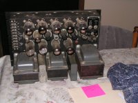
When It arrived, I tested it and it works. Took it apart just to see what is inside. This thing is built like a tank. 3X 807's for pass tubes, 2 large PC boards with several tubes on each. Monster transformer! The regulation is excellent and it goes up to 550 volts!
Shipping was a flat rate $45. I believe the particular seller is making some good money on shipping, but at least in my case he had to ship it from California to Florida.
Even so $70 was a good deal for this power supply since people are paying $100 for Heathkit power supplies.
Even so $70 was a good deal for this power supply since people are paying $100 for Heathkit power supplies.
Warm, yes it gets warm in here when I turn too much stuff on. Fuzzy, yeah some of my amps sound like that.
Actually I needed more voltage than my Knight can put out. The home made HV power supply is just too physically large to fit my small bench, so I am rebuilding it. I got a surplus 1500 volt transformer. I will feed it with a 4 amp variac and follow it with a SS bridge and filter for a simple 0 to 1800 volt bench supply. I should be able to fit this into a small box.
I will keep the Fluke, the Knight, the new HV supply, and my two SS low voltage supplies for filaments op-amps and other SS experiments. I have a 0 to 20 volt, 50 amp monster under the bench for simulated car battery experiments. You can never have too many power supplies, I would have more if I had the space for them.
It seemed for the longest time I could not find a power supply for my tube project and then BAM they started presenting themselves. I ended up w/ two; the first one is a Lambda model 71, beautiful in both condition and performance. Two weeks later a Hewlett Packard 712B became available on Ebay and I couldn’t resist. 45.00 dollars plus 45.00 for shipping, both are 500V @ 200mA w/ a panel variac for the HV control. The 712B manual states that an additional 300 volts (800 total) can be available by connecting the load across the +HV and -300V 50mA bias supply. Both of these power supplies are 50+ years old and all that was needed were two binding post replacements for the 712B. The combined weight of both is 120 lbs. Unbelievable how well these boat anchors were made.
I’m sure this is a long shot but I’d be willing to trade one of them for a HP distortion analyzer or Tek 465 scope if anyone is interested.
Stan
I’m sure this is a long shot but I’d be willing to trade one of them for a HP distortion analyzer or Tek 465 scope if anyone is interested.
Stan
- Status
- This old topic is closed. If you want to reopen this topic, contact a moderator using the "Report Post" button.
- Home
- Amplifiers
- Tubes / Valves
- Benchtop PS