I am planing on building the amp on diy paradise and I have a problem with the PS. For those of you who don't know this amp here is the url
http://diyparadise.com/simpleel84.html
My problem is that I want to build this w/o the choke and I don't know how. I am doing this so I can make this amp for very cheap.
http://diyparadise.com/simpleel84.html
My problem is that I want to build this w/o the choke and I don't know how. I am doing this so I can make this amp for very cheap.
TANSTAAFL! You could use a trafo with a slightly higher rectifier voltage and a CRC, instead of a CLC, filter. Breaking the filter up into CRCRC could help too.
Also, use UF4007 diodes. They cost 15 cents each and are MUCH less noisy than 1N4007s are. The snubber filter between the diodes and the power trafo stays.
Also, use UF4007 diodes. They cost 15 cents each and are MUCH less noisy than 1N4007s are. The snubber filter between the diodes and the power trafo stays.
"TANSTAAFL! You could use a trafo with a slightly higher rectifier voltage and a CRC, instead of a CLC, filter. Breaking the filter up into CRCRC could help too."
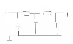
Could you draw a wiring diagram of this? I can read a diagram but other then that I am a bit lost.
As for the rectifier, I don't mind spending money for good ones. Are there better then UF4007 or should I just use those?
Could you draw a wiring diagram of this? I can read a diagram but other then that I am a bit lost.
As for the rectifier, I don't mind spending money for good ones. Are there better then UF4007 or should I just use those?
As for the rectifier, I don't mind spending money for good ones. Are there better then UF4007 or should I just use those?
You will do FINE with UF4007s. The snubber filter will kill off the small amount of noise they produce. You could boost performance of the snubber by using a 100 nF. cap., instead of a 10 nF. cap., across the power trafo's secondary. Snubber caps. need to be HIGH WVDC rated, as there are spikes to be dealt with. 1200 PIV Silicon Carbide (SiC) Schottky diodes would be a step up, but they are as expensive as filter chokes. A snubber is not needed if Schottkys are used.
I do schematics by hand and it's hard for me to post them. Perhaps another "denizen" will provide a CRCRC filter drawing.
I am going to stick with CRC for now, I think. Should I still use 100uF caps for this or go larger? If I were to go with a CRCRC what size resistors would I use and what caps?
What is the main bennifit from switching from a CRC to a CRCRC?
On the schottky's I have looked but I don't see any that cost as much as the $30 choke. Am I looking at the wrong thing on mouser?
What is the main bennifit from switching from a CRC to a CRCRC?
On the schottky's I have looked but I don't see any that cost as much as the $30 choke. Am I looking at the wrong thing on mouser?
The PIV rating of the Schottky diodes Mouser carries is WAY too low for B+ PSU duty. Cree 1200 PIV SiC parts are in order and they cost over $10 each. Parts Connexion carries Cree SiC Schottky diodes.
Parts Connexion
BTW, if the B+ supply was bridge rectified, lower cost 600 PIV parts could be used. 4X 600 PIV parts cost less than 2X 1200 PIV parts and there are multiple manufacturers.
Parts Connexion
BTW, if the B+ supply was bridge rectified, lower cost 600 PIV parts could be used. 4X 600 PIV parts cost less than 2X 1200 PIV parts and there are multiple manufacturers.
For the PS caps will these work?
http://www.partsexpress.com/pe/pshowdetl.cfm?&DID=7&Partnumber=020-1458
or am I looking at the wrong kind of cap?
http://www.partsexpress.com/pe/pshowdetl.cfm?&DID=7&Partnumber=020-1458
or am I looking at the wrong kind of cap?
You are looking at the right kind of cap., but you should use 400 WVDC parts for a substantial margin of safety.
Buy your caps. from Mouser along with Fairchild UF4007 diodes.
Use the CRCRC topology with 3X 100 muF. caps. and 2X 150 OHM wirewound resistors. Mouser carries suitable resistors.
Buy your caps. from Mouser along with Fairchild UF4007 diodes.
Use the CRCRC topology with 3X 100 muF. caps. and 2X 150 OHM wirewound resistors. Mouser carries suitable resistors.
hacknet said:don't mind me asking but why is there a preference for a CRC filter compared to a CLC filter, i always thought a CLC filter was superior to a CRC in hum reduction and power supply impedance.
Thanks!
CLC is BETTER. CRC is lower in cost. It's a matter of money.
")
Eli Duttman said:
CLC is BETTER. CRC is lower in cost. It's a matter of money.
And sometimes a matter of space!
CRC is smaller (usually).Sherman said:
And sometimes a matter of space!
BTW what is the acoustical trade of with CRC? less transparent?
navin said:
BTW what is the acoustical trade of with CRC? less transparent?
I honestly haven't been able to hear a difference in a well done CLC and a well done CRC.
You can get extremely smooth B+ with sufficient CRC filtering, and you can get extremely smooth B+ with chokes.
The electrical tradeoff on CRC vs CLC is in regulation. A CRC will droop more in a heavy load than the equivalent CLC. Its acoustic effect will depend on the amps topology and use, its a much bigger deal in an AB amp than an A as the voltage drop will vary. Some instrument amps have deliberately droopy rails.
Ok I am looking at the schematics and the pair of output tubes and they look like there are 4 wires connecting the tubes to the output transformer. My output transformers only have three input wires. Two were connected to the tubes on the old amp and one to b+ for UL. How do I use this ouput transformer correctly?
DJNUBZ said:Ok I am looking at the schematics and the pair of output tubes and they look like there are 4 wires connecting the tubes to the output transformer. My output transformers only have three input wires. Two were connected to the tubes on the old amp and one to b+ for UL. How do I use this ouput transformer correctly?
Your output transformers do not have a UL tap. The B+ connection is not a UL connection. The schematic shows the tubes connected for UL operation.
For your OPT's you can connect it in either triode mode (triode strapped) or pentode mode but not UL. For triode mode connect a 100 ohm resistor to G2 and then connect the other end of the resistor to the anode then connect the anode to the OPT.
For pentode mode connect G2 to the B+ (the B+ is still also connected to the OPT). You also still connect the anode to the OPT.
- Status
- This old topic is closed. If you want to reopen this topic, contact a moderator using the "Report Post" button.
- Home
- Amplifiers
- Tubes / Valves
- newb needs help on simple el84 amp PS