dr._sleep said:How does one calculate the load an input tube is working into when the next stage is a power tube, cap coupled?
How about the Aikido input tube, its loaded by the other half of the tube?
thanks,
dr._sleep
I assume you mean AC load (the DC load is different). Is the power tube into grid current? That is a load for the driver (or prestage). If not, you have - for AC - everything in parallel to make up the load: pre tube anode load, next stage grid resistor, whatever. Remember, for this calculation, for AC, the B+ and ground are the same, and the cap can be seen as a short. Any impedances to either B+ or ground, on either side of the cap, are in parallel.
Jan Didden
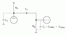
(See attached)
The load of the next stage grid is composted of the grid resistor in parallel with the specified capacitances: the grid-to-cathode capacitance, plus the Miller capacitance from: C(miller)= Cgp(1 + Av), plus the inevitable stray capacitance. The latter can be guesstimated as 30pF (you can't make it much less, but you can make it considerably more with poor construction techniques).
For the low frequency end of the audio range, the tube capacitances can be ignored. At the high frequency range, these become important and it is necessary for your driver to be able to supply those additional currents if you are to avoid slew rate distortion. If you don't go into grid current, then just about any medium u tube operated a sane load line should provide that current to any pentode or beam tetrode operated as pentodes/tetrodes. (High u tubes may not have enough moxie to drive a power tube directly, so you can use a cathode follower for adequate power grid drive.) This can possibly become problematic if triodes are used, as power triodes typically have larger Miller capacitances.
Of course, classes that require grid current have the additional load represented by the resulting grid current. In those cases, you probably need xfmr coupling or something like a power MOSFET to supply the necessary grid power. And that's a whole 'nother story.
Attachments
- Status
- This old topic is closed. If you want to reopen this topic, contact a moderator using the "Report Post" button.
