Hello!
What would be a reasonable amount of ripple to aim for when designing a power supply (in percentage of ht voltage or in mV)? This is probably different for various amplification stages - some rough approximations from some more knowledgeable builders would be very welcome for single-stage preamps & single-ended power amps (driver stage + output stage). Seems ripple is a factor that demands curing by higher capacities in ps (I'm already using enough chokes)...
BTW: Is hum the only significant symptom of power supply ripple or is there more to it than that?
Many thanks!
Rough rule-of-thumb for SE:
Determine how much hum is acceptible according to your speaker efficiency and listening conditions. For me it's 1mV. Multiply that by the OPT ratio to dermine the maximum +B ripple for the output stage.
Earlier stages are potentially more sensitive, as the hum gets amplified by following stages. However, because the current draw is less, it's quite easy to add enough C to get a quiet stage. Some topologies are less sensitive to hum: CCS and mu-followers.
Adding extra C can bring more hum in some cases. These are where the existing earthing scheme is incorrect. Make sure all earth currents flow individually to a central point.
There are extra reasons for hum with SE using DHT's, but that's another ramble..
Hi John,
Don't think I'm getting it If I take the same 1mV * 625 (5k to 8ohms opt) I get a max. ripple of 625 mV - seems very high to me! Someone suggested around 70mV shouldn't be exceeded for the ps of a el84 se in triode mode - I simulated a ps for my 6080 se and it has around 25mV on B+ for output stage.
Do you also have an approximation for driver stages? The same 6080 amp has got around 2,5mV on it's driver stage - / How do I mathematically combine the ripple of driver and output stage to get the actual amount of ripple reaching the speakers?
Thanks for the tips!")
Don't think I'm getting it
If I take the same 1mV * 625 (5k to 8ohms opt) I get a max. ripple of 625 mV - seems very high to me! Someone suggested around 70mV shouldn't be exceeded for the ps of a el84 se in triode mode - I simulated a ps for my 6080 se and it has around 25mV on B+ for output stage.Do you also have an approximation for driver stages? The same 6080 amp has got around 2,5mV on it's driver stage - / How do I mathematically combine the ripple of driver and output stage to get the actual amount of ripple reaching the speakers?
Thanks for the tips!
Well I think I'm right, it's what I've used. Please someone correct me or confirm.
For the driver stage I've used the same ratio, but multiplied by the amplification factor of the output valve. Of course if an IT is used, it's ratio also needs to be accounted for.
I believe that you have to consider the worst case in adding ripples; that they are in-phase. In practice they won't be and thing will (probably) be better than predicted in RMS, but the actual resultant waveform may sound more abrasive.
Hello,
If the PS voltage is 300 volts, .6 volt ripple is pretty good, actually. Remember please that the output stage is being fed usually directly from the B+, where preamp and driver stages have additional RC filtering.
Myself, I try to get ripple as low as noise. About 1 or 2 mV P-P at the B+.
I acheive this by using about 10 percent of the highest value for the plate of the rectifier for the first capacitor. For a 5Y3 for example that is about 35 uF. So use 25-30. Then a decent choke. Doesn't have to be that large, really. Just one that can handle a decent current. I use 1.5 H at 200 mA. Then a nice hefty cap after.
I generally determine this by calculating the impedance of the amp at the lowest frequency response at which I want the amp to perform. For instance, if the impedance of the amp at full power (for single ended one channel) is say 106 volts at 50 mA, then the impedance is 212 ohms (106/0.5). I then use the old standard of 1/10th of 212, or 21 for the capacitive reactance. Plugging that into the formula for cap reactance at 20 hertz, I come up with [1/(2*Pi*F*Xc)]=1/(2*3.14*20*21)=1/2637=379uF! Of course, you can use half of that with decent enough results. And a 150 uF cap is cheaper than a 350 uF one.
I use 20 Hz because the cap not only filters ripple, but keeps the amp from feeding back audio through the B+ line to other stages.
Ripple on the driver stage may not be a factor. If you look on the plate, it may not even exist there. If it is not there, it is not on the cathode, which would then be amplified by the tube (the cathode can be an input as well as an output), therefore not being fed to the rest of the amp.
Some amplifiers take advantage of the tube's sentitivity to hum from the heater this way. The tube amplifies the hum via the cathode, which hum is then actually cancelled by B+ hum at the plate. That is how the AC/DC radio deals with hum, as well as direct heated cathode tubes. That is why adding more capacitance to the B+ causes an increase in hum in those cases, because there is then not as much B+ hum to cancel out the heater/filament based hum, hence the need for and why it is called a hum balance pot. Fun ways to make cheaper tube equipment!
As for calculating... if you have an oscilloscope, then just use that. But generally, if the preamp/driver has ripple and it is being amplified (key), use teach stage's gain (a difficult formula to use) to calculate that. Otherwise, just use your ears. Listen and make changes until hum is all but gone.
My
Gabe
Expanding a bit on what dhaen started:
There will be a small reduction of power supply ripple by the PSRR of the amplifier itself but is not very important for an ordinary transformer coupled amplifier, however for small signal amplifier the PSRR help us very much with ripple reduction.
The ripple on the anode will be reduced by the ratio of the output transformer but it is the voltage ratio that is important, not the impedance ratio. If we use the example transformer with 5kohm primary impedance and 8 ohm secondary it has an impedance transformation ratio of 5000/8 = 625 but the voltage transformation ratio is only SQRT(625) = 25.
The result is that in order for us to have a ripple on the 8 ohm output of 1mV we need to ensure that the power supply doesn't give more than 25mV a quite low level and evidence of that a single ended class A amplifier need a quite good filtered power supply.
Similar calculations can and should be made for each amplifier stage but it is important to put reasonable requirements at the beginning, it is often not that difficult to get very good performance even when using normal value components. I have used CRCRC... chains in power supplies for preamplifiers with very good effect although I used quite small capacitors.
Regards Hans
A few more factors:
Pentodes reject hum on the plate supply better than triodes, but NOT at the screen - the screen is an INPUT GRID too - its supply has to be well filtered.
Push-pull gives about 10X hum cancellation - sometimes the tipoff on a weak output tube is the hum due to unbalance...
Earlier stages need hum reduction in proportion to the gain that follows. So if the output stage has a gain of 10, the driver needs 10X less hum to be acceptable. But usually a decoupling network provides this. If you want to know why it's called a DEcoupling network, try building a 3-stage amplifier without it! In a 2-stage amplifier, the feeback through the power supply is negative... in a 3-stage, feedback from the last stage to the first is POSITIVE... can you say motorboating?
That explains it
John, may I ask how sensitive the speakers are that you want max. 1mV hum on? Mine are around 96dB/W and my ears are around three meters removed from the cones.
Tom, do you mean what I call coupling caps when you say decoupling caps = The things that couple ac from one amp stage to another but block dc? --- Does that mean that in reality the hum level in a C-coupled driver stage doesn't matter (so no need to multiply by the gain ratio and calculate the ripple for knowing the hum-level) -- but maybe the stage suffers from other downsides of a non-stable voltage supply (intermodulation distortion etc.)? (Just letting my thoughts flow )
John, may I ask how sensitive the speakers are that you want max. 1mV hum on? Mine are around 96dB/W and my ears are around three meters removed from the cones.
Tom, do you mean what I call coupling caps when you say decoupling caps
= The things that couple ac from one amp stage to another but block dc? --- Does that mean that in reality the hum level in a C-coupled driver stage doesn't matter (so no need to multiply by the gain ratio and calculate the ripple for knowing the hum-level) -- but maybe the stage suffers from other downsides of a non-stable voltage supply (intermodulation distortion etc.)? (Just letting my thoughts flow )Kilmon, my speakers are 91dB/W: Diatone DS-35B , but the room acts as a horn to amplify LF. It height ramps from 2m (where the speakers are sited) to nearly 6m...Yes it's a strange house!
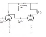
Coupling caps transfer the signal from one stage to the next. Decoupling caps "couple" the signal to ground, such as signal that may be present on power rails. This would otherwise cause unwanted feedback and instablility.
This is not precise use of language however. If you look carefully at your schematic you will find the signal's return path is often through the "decoupling" caps. This is why it makes no sense to spend $$$ on coupling caps without considering the return path too. (In my view it hardly makes sense anyway)..
Hi John,
Aha, then the decoupling caps in a single-ended amp are the last caps (for each stage) in the power supply / the only ps caps directly connected to the opts in an output stage? I use small value pio caps for that purpose (around 10-15µ / channel) and small value Russian military teflon in oil caps (0,1 or 0,056µF; calculated for 5-7 hz) If I'm still not talking nonsense; I once swapped cheap mkp decoupling caps in a push-pull for pio and there was a definite improvement - maybe not as much as the coupling caps but both are in the signal path I gather (although most of the ps of an amp is not but redesigning makes a world of difference ) // Do you use flea-powered sets on your Diatones? Today I tested a two-watt amp + preamp (gain = 6) on a pair of 89dB/W tml's and to my surprise I only needed about half of the available power to drive the speakers to good soundlevels???
Aha, then the decoupling caps in a single-ended amp are the last caps (for each stage) in the power supply / the only ps caps directly connected to the opts in an output stage
? I use small value pio caps for that purpose (around 10-15µ / channel) and small value Russian military teflon in oil caps (0,1 or 0,056µF; calculated for 5-7 hz) If I'm still not talking nonsense; I once swapped cheap mkp decoupling caps in a push-pull for pio and there was a definite improvement - maybe not as much as the coupling caps but both are in the signal path I gather (although most of the ps of an amp is not but redesigning makes a world of difference ) // Do you use flea-powered sets on your Diatones? Today I tested a two-watt amp + preamp (gain = 6) on a pair of 89dB/W tml's and to my surprise I only needed about half of the available power to drive the speakers to good soundlevels???Klimon said:Hi John,
Aha, then the decoupling caps in a single-ended amp are the last caps (for each stage) in the power supply / the only ps caps directly connected to the opts in an output stage
Decoupling caps are generally used in the B+ line before it connects to the plate resistor of the input and/or driver stage. The purpose is to provide an AC path to ground. Any signal that gets put onto the B+ should follow the cap to ground and not enter the tube.
Often the output stage is not decoupled.
Attachments
Hi Klimon, here is an answer taken from Norman Crowhurst's Inductance manual, it goes back a bit (1948) but from the answer you can plumb in various values:
XC = 1000000/2pi fc Reactance of a capacitor
XL = 2pi fL Reactance of an inductor
If a smoothing circuit is required to reduce ripple voltage by 1/40th of that across the reservoir capacitor, then the required ratio of reactance of smoothing choke and capacitor will be given by xc/xL =1/40.
Assuming an 8mfd capacitor is to be used, then its reactance to a ripple voltage of 100 Hertz (the predominant frequency from a 50 Hertz full wave rectifier) will be: 1000000/2x3.14x100x8=200 ohms approx.
Therefore the reactance of the choke must be 40x200 or 8000 ohms.
From the formula, 8000=2pi100L, therefore:
L= 8000/2x3.14x100 = nearly 13 Henries.
I use this formula all the time using different values, I hope it helps you.
Phil.
Hi Phil,
In the example you gave, would a 25H choke let through more ripple than the 13H choke? (Uptill now I thought that for ripple-killing more H is simply quieter). Would a 10H choke be better than a 25H because it's closer to 13H? If the answer is positive to all these questions, that's a very handy formula!!!
@Sherman: that's indeed what I meant! Haven't seen an output stage without a decoupling cap though
Simon
- Status
- This old topic is closed. If you want to reopen this topic, contact a moderator using the "Report Post" button.
- Home
- Amplifiers
- Tubes / Valves
- Ripple guidelines for power supplies