How do you prototype a circuit? I've seen tube sockets laying on a workbench, old chassis with sockets mounted temporarily and some things I would be afraid to go near!
Up to know I've come up with a circuit, either someone else's schematic or my own map and layed it out in PSUD II, SE Amp CAD and Tube CAD. If those looked reasonable I built it in "final form" on a real chassis the tweaked parts if necessary.
I'd like to set up some more flexible system for testing circuits but have it be "relatively safe". I don't mean totally enclosed and shielded but better than laying the sockets on my workbench while running 400V through them.
Another question I have on this topic is can I use alligator clip test leads for assembling the circuits and operating them for short periods of time (one or two minutes while voltages stabilize and filaments come up to operating temperature)? And since the test leads I see at Radio Shack or Fry's are probably made with wire rated at 300V or less what about making my own set with 600V wire?
Thanks for your input!
Hi Sherman,
I wire things up in a chassis. I use a regulated DC supply for the B+ and I get to wire with real 600V wire.
Look at www.tubelab.com under design aids, The Tubelab. Tubelab is a member on the board. I'm sure he will have some good suggestions. He prototypes a lot. The way that it scares you.
-Chris
I wire things up in a chassis. I use a regulated DC supply for the B+ and I get to wire with real 600V wire.
Look at www.tubelab.com under design aids, The Tubelab. Tubelab is a member on the board. I'm sure he will have some good suggestions. He prototypes a lot. The way that it scares you.
-Chris
At one time I decided to build a prototyping system, since I have many ideas, and only a few of them actually work. The first generation was nothing more than tube sockets screwed down to a piece of wood. Interconnection was made using Radio Shack clip leads.
The second generation was built in a wooden box, with a cover (which I never used). The wood base was covered with a layer of copper screen which was tied to circuit ground and earth ground. Each "module" was a circuit board with one or two tube sockets on it. The tube sockets were wired to Fahnestock clips (available from Mouser), so that interconnection was made with insulated wire or the component leads themselves. I still wound up using clip leads for some interconnection.
There are pictures of it here:
http://www.tubelab.com/The_Tubelab.htm
This thing is big, almost three feet wide. It takes up too much of my bench space, so I am building a new one. Same basic idea as before, but the modules are smaller. The modules are similar to these, except that I put the tube sockets on the other side of the board:
http://www.iagaudio.com/products.asp?id=3
I still use the Radio Shack clip leads for interconnection and have not had any problems. They will melt if they touch a hot tube however. I made some of my own for use on high voltage circuits, and for use around hot tubes. I used Teflon wire, it doesn't melt.
I prefer this type of open prototyping system because it allows for quick circuit changes. It is however inherently dangerous, and safe operating procedures must be used around it. I will connect all meters, scope probes, and signal sources up to the circuit before applying power. I stand a safe distance away while the circuit is live. I will always have the circuit "doubly disabled" when working on it. This means power strip off AND power supply unplugged. This makes it impossible to accidentally power up.
If you don't like the open arangement, mount the individual modules on the under side of a piece of thin wood or metal such that the tubes protrude through holes in it. Then mount the whole thing on some type of enclosure using hinges. All wiring and components are under the lid, which is opened up for circuit modification. You could even add an interlock to disable power when opened.
EC8010 said:Is this scary enough? It was a 5W amplifier that wasn't terribly good. So it's just as well it didn't take long to make.
SY said:A constant current diff amp.
Yeah! Those are the kind of scary things I was hoping to avoid!

It looks like I'm not risking my life using RS clip leads so I'll probably get a couple more sets. And I did start looking for an adjustable power supply (like the Knight on Tubelab's site) to handle PS chores.
Sherman said:It looks like I'm not risking my life using RS clip leads...
Yes, you are. The thing about those horrible lash-ups is that they were built and tested in full knowledge of their danger. I am extremely nervous about electricity. It's nasty stuff, and it kills. When I knock up something as dodgy as that I surround it with test equipment and don't go near it when it has power. I wind up the HT very carefully and monitor both the HT current and voltage as I do so. I shut everything down at the slightest hint of an irregularity.
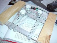
I've made several different phono stages and a couple different line stages in the past few years and I didn't want to entirely rebuild everything each time so here's what I did. There are small (about 4 x 6") steel plates available at Home Depot in the timber framing section and I bought several of these over time. I have a partial chassis that contains some terminal strips (screw-type) which connect to the umbilical cord to the power supply I built for these projects. The partial chassis is like a shadow box or deep picture frame, it is basically an aluminum box with no top and about 3" deep.
When I build a new circuit module I just have to punch holes for the sockets and attach a few lug-type terminal strips in one of the plates. The "frame" has some screws that hold down the edges of the plates and so the whole thing is both well-enclosed and also easy to monkey around with. I add some wiring with spade lugs to connect to the screw terminals for B+, ground & filament connections.
This has been pretty flexible and has worked well so far. But it is kind of ugly.
Here's a photo. In the photo, the front plate is an Aikido line stage using 6SN7's and the rear plate is one of my 6C45P phono stages, I'm not sure which one:
-j
When I build a new circuit module I just have to punch holes for the sockets and attach a few lug-type terminal strips in one of the plates. The "frame" has some screws that hold down the edges of the plates and so the whole thing is both well-enclosed and also easy to monkey around with. I add some wiring with spade lugs to connect to the screw terminals for B+, ground & filament connections.
This has been pretty flexible and has worked well so far. But it is kind of ugly.
Here's a photo. In the photo, the front plate is an Aikido line stage using 6SN7's and the rear plate is one of my 6C45P phono stages, I'm not sure which one:
An externally hosted image should be here but it was not working when we last tested it.
-j
Hi J Epstein,
Hey, I like that idea. I think I'll build up something similar.
Like EC8010, I watch the voltage and current like a hawk when powering up. Been zapped once too often. Usually by a test clip that goes "ping" and off. I wired up some with real test clips (Mueller) and 600V wire as a result of this. They helped but things still fall off.
-Chris
EC8010 said:
Yes, you are.
... I am extremely nervous about electricity. It's nasty stuff, and it kills. When I knock up something as dodgy as that I surround it with test equipment and don't go near it when it has power...
I guess if you look at it objectively we are all risking our lives doing this, at least to some extent!
Your turn-on procedure for a test rig sounds a bit like what I do. I usually hook up a couple meters so they are visible from my position 10-12 feet away when I apply power. I also wear rubber soled shoes and I have a big resistor on an insulated handle to discharging caps.
J Epstein said:
...here's what I did. There are small (about 4 x 6") steel plates available at Home Depot in the timber framing section and I bought several of these over time. I have a partial chassis that contains some terminal strips (screw-type) which connect to the umbilical cord to the power supply I built for these projects. The partial chassis is like a shadow box or deep picture frame, it is basically an aluminum box with no top and about 3" deep.
...
-j
Great idea! I'll have a look at those next time I'm in Home Depot.
If you think about it, you are taking a bigger risk by driving to work every day. At least here in South Florida!
If You use the RS clip leads, think of them as being un-insulated. Try to keep the ones that carry more than a few volts away from each other, and ground (and obviously yourself).
After thinking a little bit more about this, I believe that I will get some of the previously mentioned turret boards, mount them to a street sign that appeared in my yard during the storm so the tubes stick up through holes and all the parts and wiring are underneath. Mount the whole thing to a wood box, so that it can be flipped over. Add some connectors for power and meters.
I just ordered the turret boards, I will post pictures when it is done.
Hi tubelab,
Sadly, there is a lot of truth to that! However, you can't be too careful around high voltages.
-Chris
If you think about it, you are taking a bigger risk by driving to work every day.
Sadly, there is a lot of truth to that! However, you can't be too careful around high voltages.
-Chris
I use anything from boards to bread pans.
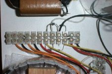
Lately I have been using these term strips from Radio Shack. They can be easily cut and screwed to a board, were needed and used in place of solder points.
I love the tube lab idea! I bet a combination of the Fanstock clips and these would work great.
Lately I have been using these term strips from Radio Shack. They can be easily cut and screwed to a board, were needed and used in place of solder points.
I love the tube lab idea! I bet a combination of the Fanstock clips and these would work great.
Attachments
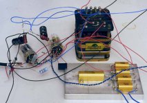
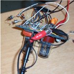
here's what I use -- there's a "BasicStamp" in there which controls my power supply:
An externally hosted image should be here but it was not working when we last tested it.
I built this power supply and "test bed" to evaluate the sound of various ST, octal and globe tubes using simple classic line and phono circuits. The power supply has filament voltages for 2v, 2.5 volt, 6.3 volt and 12 volt tubes and 2 seperate LCLC B+ outputs. Now I am working on a balanced Akido and I decided to go for broke and just built it in its "final" form and tweak as needed. I will post pics of it when I get it working
Dave
An externally hosted image should be here but it was not working when we last tested it.
An externally hosted image should be here but it was not working when we last tested it.
Dave
EC8010 said:
Yes, you are. The thing about those horrible lash-ups is that they were built and tested in full knowledge of their danger.
What EC and tubelab said. Test clips are never attached or removed (even from ground!) with any power present. Power supplies are ramped up, and there's current limiting for the inevitable mistakes (like backward diodes or electrolytics).
"Yes, you are. The thing about those horrible lash-ups is that they were built and tested in full knowledge of their danger."
This is good, so is fear. If you don't sense some of both the first time that you plug in "the big one" you shouldn't be playing with electricity. It must be respected.
When I performed the 833A experiments shown on my web page, there was a 1/4 inch thick sheet of Lexan between me and the electricity. I had one hand on the KILL switch (you should have one) and a FIRE EXTINGUISHER in the other hand! Fortunately neither were needed, the amp worked the first time. There will be times (for all of us) where experiments won't go as planned. The likelyhood for ugly stuff goes up quickly with the power supply voltage. BE PREPARED!
I have been playing with vacuum tube electronics for over 40 years, and have had to learn some of these things the hard way. I have had an associate rushed to the ER from near lethal shocks (25KV laser power supply). Fortunately I have never been severely shocked from my experiments (got knocked stupid by lightning once). From these experiences, I have learned how to minimize the risk, and outlined the information on my web site. Unfortunately that page gets very few hits.
http://www.tubelab.com/Safety.htm
Tubelab,
Excellent safety article (I just incremented your hit ticker). I agree 100% with your material, except the lethal current can be even lower, in the micro amp range. The involuntary muscle contractions and injury due to this is often the most serious injury. And yes, I've been nailed due to unexpected, abnormally high voltages due to circuit failure. Exploding parts are another danger you've done a good job pointing out.
Really good work. Anyone joining the "tubes" area should be forced to read this. At least have it emailed to them (if possible). I have the distinct feeling many in this forum are not trained and have not read the DIY safety sticky,
-Chris
term strips
Now I know their English name. I'm also planning to use those in preamp, poweramp, IV - stage duties. I have 'assembled' some prototypes - see the pictures. I've not done any real test yet.
Erik
Attachments
- Status
- This old topic is closed. If you want to reopen this topic, contact a moderator using the "Report Post" button.
- Home
- Amplifiers
- Tubes / Valves
- Setting Up a Circuit for Testing