Mark A. Gulbrandsen said:Above I should have said the second half is not sinking anything at all.... No LED!
replace IRF 820 from shunt part in CCS part-just to check its burned or not;
you can use even TL07x (08x) as substitute,for testing ;I dunno for stability versus LF.... but for test it will be OK
hehe- orientation of pins for irf-same as in your's Aleph's output stage,biasing too........
did you checked what you get on inputs of OP?
you didn't swapped plus and minus OP input?
plus goes on voltage ref (pin 2)
minus on voltage sens divider (pin 3)
what voltage you have on pin2?
what voltage you can set on pin3?
somewhere there is catch22")
at least to my knowledge,max voltage you need to achieve at output of OP is ....hehe....full throttle .....Uled + voltage for open mosfet....~ 3 +4 V.....coincidently-almost same as voltage reference.......
plus goes on voltage ref (pin 2)
minus on voltage sens divider (pin 3)
what voltage you have on pin2?
what voltage you can set on pin3?
somewhere there is catch22
at least to my knowledge,max voltage you need to achieve at output of OP is ....hehe....full throttle .....Uled + voltage for open mosfet....~ 3 +4 V.....coincidently-almost same as voltage reference.......
Here are the voltages...
Pin 1 n/c
2 7.09
3. 6.38 to 7.58 depending on pot setting
4. Gnd
5. .68 to .210 Seems too low to me...
6. N/C
7.15.00
8. N/C
Pin 2 is obviously seeing the 7 volts + refrence. Seems like the comparator is not functioning correctly. I even disconnected the drive out(pin 5) to see if it would climb at all. I've changed the IC once already! Also it is definately wired correctly.. been over it a dozen times .
.
Mark
Pin 1 n/c
2 7.09
3. 6.38 to 7.58 depending on pot setting
4. Gnd
5. .68 to .210 Seems too low to me...
6. N/C
7.15.00
8. N/C
Pin 2 is obviously seeing the 7 volts + refrence. Seems like the comparator is not functioning correctly. I even disconnected the drive out(pin 5) to see if it would climb at all. I've changed the IC once already! Also it is definately wired correctly.. been over it a dozen times
.Mark
Mark A. Gulbrandsen said:Here are the voltages...
Pin 1 n/c
2 7.09
3. 6.38 to 7.58 depending on pot setting
4. Gnd
5. .68 to .210 Seems too low to me...
6. N/C
7.15.00
8. N/C
Pin 2 is obviously seeing the 7 volts + refrence. Seems like the comparator is not functioning correctly. I even disconnected the drive out(pin 5) to see if it would climb at all. I've changed the IC once already! Also it is definately wired correctly.. been over it a dozen times
Mark
is it the same if you use 30V on pin 7,instead 15 V ?
if you can't use higher voltage than 15V, try to decrease these 10K resistors to 5K ;
start with resistor in series with zenner
EDIT: just saw your post about pinout mess,while I typed -you posted that.........
Mark : http://www.diyaudio.com/forums/showthread.php?postid=941311#post941311
moral of the story:
always triple check pinouts..........you repair things,,for living-amongst other activities ?......I learned that -in a hard way..........you can imagine mess with pinouts ,when you live in area with parts from all over the world....including West and East.......
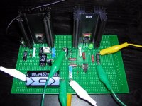
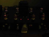
Hey Geek......I wonder if I just found your problem too??? Mr Wright has some Wrong things in his Cookbook on the Wregulator diagram thats for sure! He DID have the output pin listed as pin 5 but it is indeed pin 6 on the chip. He also has the pass devices drawn wrong. I believe the arrow on the MOSFETs is supposed to go the other direction! I had to change the IC and shunt device and LED again as I believe hooking the drive output up to pin 5 cdamaged the 351. When I moved it to pin 6 it powered up for a flash of the LED and then quit, the shunt device had shorted.
As you can see the LED is now lit up and all things are happy!
For 50 ma draw I think the drive voltage on pin 6 was about 11.5 volts or there abouts. The sink got a bit warmish at 50 ma. When I actually hook it all up I will post all of the correct votage readngs.
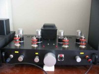
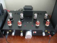
The finished unit below...... Won't have time for a couple of weeks to hook it up though as I'm off on a trip to Montana tommrrow for a while.
Thanks Choky for all your help with this! It just goes to show that even Mr. Wright can also be Mr. Wrong.....
Mark
As you can see the LED is now lit up and all things are happy!
For 50 ma draw I think the drive voltage on pin 6 was about 11.5 volts or there abouts. The sink got a bit warmish at 50 ma. When I actually hook it all up I will post all of the correct votage readngs.
The finished unit below...... Won't have time for a couple of weeks to hook it up though as I'm off on a trip to Montana tommrrow for a while.
Thanks Choky for all your help with this! It just goes to show that even Mr. Wright can also be Mr. Wrong.....
Mark
Attachments
choky said:
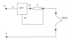
use two 5s in series,then use good ole 317 as CCS , adjust for needed current in range of 6V3 (~600mA).........
and ,yes,use one 317 per tube
Hi Choky, I tried using the CCS on heaters for my 5687WB headphone amp. It has 14V winding which is bridge-rectified. I had set the 317CCS to ~0.45A using a 2.8R. I do see the slow rise in voltage at turn on, but it rises to over 13V too... so I quickly shut off the mains... did I do something wrong here?
Mark A. Gulbrandsen said:Hey Geek......I wonder if I just found your problem too??? Mr Wright has some Wrong things in his Cookbook ..................................
Mark
me again.........
that is one good point for all Cookbooks :
use recipe only as basic thing for your thinking and rethinking ;
do not use any (really not proofed) recipe as gift from heaven......think twice or trice ,check every thing-with learning and understanding as only purpose ;then you'll be capable to make your own construction...no matter it is new or old......like in Jazz-your version of good Standard
I'm glad that your led is lit
btw-you didn't remember how you oriented output mosfets in your Aleph? you really don't need that arrow to help you
pengboon said:
Hi Choky, I tried using the CCS on heaters for my 5687WB headphone amp. It has 14V winding which is bridge-rectified. I had set the 317CCS to ~0.45A using a 2.8R. I do see the slow rise in voltage at turn on, but it rises to over 13V too... so I quickly shut off the mains... did I do something wrong here?
evidently you do something wrong
drawing of exact CCS schematic?
like this:
edit:
5687 is like ECC or 12A*7 series-with 6,3V (12V6) as main value,and current is of secondary importance,so you'll see that tubes from various factories have various working currents at same voltage.
don't worry if you are somewhere in range of 12V6 ; just trim (decrease) 2E8 resistor to have exact 12V6
for instance-contrary to 5687 and siblings-
P series of tubes (in European nomenclature) are "current oriented" ; there your goal is 300mA exactly-nobody really cares about voltage
Attachments
Mark A. Gulbrandsen said:Hey Geek......I wonder if I just found your problem too??? Mr Wright has some Wrong things in his Cookbook on the Wregulator diagram thats for sure! He DID have the output pin listed as pin 5 but it is indeed pin 6 on the chip. He also has the pass devices drawn wrong. I believe the arrow on the MOSFETs is supposed to go the other direction! I had to change the IC and shunt device and LED again as I believe hooking the drive output up to pin 5 cdamaged the 351. When I moved it to pin 6 it powered up for a flash of the LED and then quit, the shunt device had shorted.
As you can see the LED is now lit up and all things are happy!
For 50 ma draw I think the drive voltage on pin 6 was about 11.5 volts or there abouts. The sink got a bit warmish at 50 ma. When I actually hook it all up I will post all of the correct votage readngs.
The finished unit below...... Won't have time for a couple of weeks to hook it up though as I'm off on a trip to Montana tommrrow for a while.
Mark
According to Mr. Wright said, the LED used in the SuperReg should be of special type which can allow for more current than the normal ones.
choky said:
5687 is like ECC or 12A*7 series-with 6,3V (12V6) as main value,and current is of secondary importance,so you'll see that tubes from various factories have various working currents at same voltage.
don't worry if you are somewhere in range of 12V6 ; just trim (decrease) 2E8 resistor to have exact 12V6
for instance-contrary to 5687 and siblings-
P series of tubes (in European nomenclature) are "current oriented" ; there your goal is 300mA exactly-nobody really cares about voltage
Thanks Choky, will check that out!
According to Mr. Wright said, the LED used in the SuperReg should be of special type which can allow for more current than the normal ones.
The LED I choose is plenty big enough for the job at hand. His LED it is stated in the book is only rated for 20 ma and he tells you to look for a larger one if you need to sink more than 20 ma continous. The first LED in my regulator blew because the driver IC was damaged due to the mistake on his diagram showing that the output pin was pin 5 instead of the correct pin #6. The output of the IC turned the shunt device on all the way, not a ogod thing! The IRF 820 then failed drawing way too much current thorugh the LED. Poof! Works fine now though....
Mark
Hi Mark,
Thanks!
I'll have to Wrevisit the circuit one day
Mark A. Gulbrandsen said:Hey Geek......I wonder if I just found your problem too??? Mr Wright has some Wrong things in his Cookbook on the Wregulator diagram thats for sure!
Thanks!
I'll have to Wrevisit the circuit one day
- Status
- This old topic is closed. If you want to reopen this topic, contact a moderator using the "Report Post" button.
- Home
- Amplifiers
- Tubes / Valves
- Yet another 12B4 line stage, or is the 12B4 better than the Grounded Grid.....