staggerlee said:
$17,000! I hope it comes with K-Y!!!
Hey, at least they include the 274B rectumfryer!

Please reccomend a choke if you would.... No, I won't try an output tranny if you held a .357 to my head!
Try a Handmade Electronics H3007 (60H @30ma): they mate very well with the 12B4 and won't break the bank.
pm
Mark A. Gulbrandsen said:I have no problem trying a choke in there, thats a sensible thing to try. I also have not tried a solid state regulator at the plate either. Someone had reccomended the IXYS type....
Please reccomend a choke if you would.... No, I won't try an output tranny if you held a .357 to my head!
Mark
Mark, do give the plate chokes a try. I have, and I ain't removing them anytime soon! I am using 100H 50mA. I have to add "wider and deeper soundstage" to what Zen_mod has mentioned too...

I had a humming on one channel initially and just could not figure it out. Until I moved my PSU choke. Orientation didn't matter, physical distance did...
lawbadman said:Does anyone have a schematic of a tube regulator circuit for the 12b4?
I have 2 OA2 tubes on hand, can they be used?
Can anyone point me to the datasheet for the oa2?
Are you going to use plate chokes? If you are, then you can use 1 OA2 on each side giving 150V regulation. If not, then you're going to need 300V and (recommended) 2 OA2s per channel (total of 4). Look for Zen_mod's schematic some posts ago...
lawbadman said:I guess I dont understand how tube regulators work, but why would I need two per channel? Dont they work like zener diodes???
One 0A2 with regulate to 150V, so to get 300V, you will need 2 stacked together as Mark mentioned. If you use plate chokes, you need only one for the required 150V.
Mark A. Gulbrandsen said:They do work like zeners.... You have to stack them in series to get the needed voltage.
Mark
Unlike Zeners they need a higher voltage to fire up, after that they drop voltage down to a regulated level. Slightly different resistors across them is the way to fire them up one by one and make resulting fire-up voltage less, if you connect them in series.
Wavebourn said:
Unlike Zeners they need a higher voltage to fire up, after that they drop voltage down to a regulated level. Slightly different resistors across them is the way to fire them up one by one and make resulting fire-up voltage less, if you connect them in series.
Could you post a rough schematic? I wasn't aware that VR tubes needed resistors across them. I do know that they need a resistor above them eg.
http://www.tpub.com/content/neets/14178/css/14178_150.htm
Thanks
zobsky said:
Could you post a rough schematic? I wasn't aware that VR tubes needed resistors across them. I do know that they need a resistor above them eg.
http://www.tpub.com/content/neets/14178/css/14178_150.htm
Thanks
Connect 2 gas tubes in series. Slowly rize voltage on them, of course through a current limiting resistor. Now connect pair of high ohm different bleeding resistors across them and compare. You may use a variac in the primary of your PT to check what voltage is needed to fire them up if you don't have a laboratory source of regulated voltage.
Alright, I will ask Zen Mod or anybody who can simulate this:
I bought a transformer just for this project to run those OO3 gas regulation tubes. Do I need a choke or filter arrangement for this transformer to run those tubes correctly???
Transformer: www.edcorusa.com Model: XPWR106
115V 60Hz. 275-0-275
125mA 6.3V, 4A
Primary Voltage:
115VAC
Primary Frequency:
60Hz
First Secondary winding:
275-0-275VAC, 125mA
Second Secondary Winding:
6.3VAC, 4A
http://www.edcorusa.com/classx/power/xpwr/Xpwr106.htm
you bought it before you know it's good or not?LuckyLyndy said:Alright, I will ask Zen Mod or anybody who can simulate this:
I bought a transformer just for this project to run those OO3 gas regulation tubes. Do I need a choke or filter arrangement for this transformer to run those tubes correctly???
Transformer: www.edcorusa.com Model: XPWR106
115V 60Hz. 275-0-275
125mA 6.3V, 4A
Primary Voltage:
115VAC
Primary Frequency:
60Hz
First Secondary winding:
275-0-275VAC, 125mA
Second Secondary Winding:
6.3VAC, 4A
http://www.edcorusa.com/classx/power/xpwr/Xpwr106.htm

which schematic?
like Mark's -with R on anode?
preliminary - that xformer is on the edge here..... if I presume that you want R loaded stage,with two OD stacked per channel.....
Mark A. Gulbrandsen said:
Same... identical as Mark's.
Mark... Mark my word on that!
in that case
xformer
then two schotkys (even from PC supply) as full wave rectifier ,common for both channels
then muuuucho of capacity
then same schmtc as for Mark's (one I drew it here..........http://www.diyaudio.com/forums/attachment.php?s=&postid=910671&stamp=1147048038
mebbe just slightly smaller resistor in front of gass toobz,just because your (Lucky's
) voltages will be smaller than 400V before gas stabzanyway-I can bet that xformer will be warmmmmmmmmmmmmm
Mark-did you tried your super reg variant?
Mark-did you tried your super reg variant?
Not yet... time factor, time is a 4 letter word. Working on KSA-100 and then this 12B4 line stage or he is going to come to hunt me down!
Mark
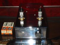
arnoldc said:I decided to put my 12B4A preamp in a different chassis-
Zen Mod, ugly enough for you?
ugly!

- Status
- This old topic is closed. If you want to reopen this topic, contact a moderator using the "Report Post" button.
- Home
- Amplifiers
- Tubes / Valves
- Yet another 12B4 line stage, or is the 12B4 better than the Grounded Grid.....