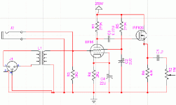
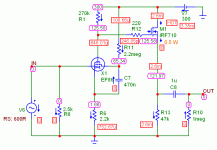
I need a microphone preamp quick, so I looked at some commercial offerings. Below €100 things aren't looking great. I think it is better to make something by myself. I have some mic transformers, a few EF86, a lot of 12AX7(ecc83), 12AU7(ecc82), some tube types I don't know and a few power transformers in the house. I would like to use the preamp with balanced and unbalanced Low-Z dynamic microphones. What do you think of the schematic I made? I'm sure that it won't explode  , but is it a good microphone preamp
Attachments
The schematic has errors. G1 of the EF86 gets the drive signal. G2 goes to the dropped B+. G3 is tied to the cathode. The volume control is in the WRONG place. Make R3 a 2.5 KOhm pot. and connect the wiper to g1 of the EF86. R2 should be a fixed 1 MOhm part. C1 should be 4.7 muF. to prevent low freq. losses. There's no forward bias on the IRF820's gate and it's an enhancement mode device. Also, a stopper resistor is strongly indicated at the FET's gate.
The FET bias problem is easily corrected. A 10 MOhm resistor connects the FET's gate to the + terminal of a 9 V. Lithium battery. The - terminal of the battery is connected to the FET's source.
I have a suggestion. Increase the B+ rail voltage. Increase the 2 load resistor values in a manner that keeps plate and drain current values unchanged. Eliminate the bypass cap. on the cathode resistor of EF86. Connect the screen grid bypass cap. to the cathode, not ground. While the EF86 is quite linear, local current NFB introduced by the unbypassed cathode resistor further linearizes the EF86. The loss in gain is made up for in the increased load resistance.
svokke said:...a few EF86, a lot of 12AX7(ecc83), 12AU7(ecc82)...
EF86 - Siemens V76
ECC83 - Elektor Feb.2003
ECC82 - Gyraf G9micpre (www.gyraf.dk)
svokke said:...
I'm unsure though why I should connect the screen grid bias smoothing cap to the cathode.
..
Because it's the screen to cathode voltage that matters. If it was connected to ground, there would be signal and PS noise superimposed on the screen. This is a very common configuration for the EF86, which was a pentode designed to be as low distortion as a triode.
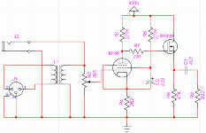
There's something I missed earlier. J2 needs to be a switching type that disconnects the secondary of the mike trafo from the "top" of the pot., when a plug is inserted. Otherwise, the trafo's secondary bypasses the volume control pot.
The EF86 is a small signal, not a power, pentode. The screen grid should be at a lower positive potential than the plate. Make the screen B+ dropping resistor 560 K or even 1 M.
I don't know if it's possible to DC couple an enhancement MOSFET to an "upstream" device. Put the coupling cap. back in and use a bias battery as I already indicated. Battery life in this application is YEARS. Use a 1 KOhm Carbon composition part as the gate stopper resistor. The body of the stopper resistor should be mounted as closely as is possible to the FET's gate terminal.
I think I should read the radiotron designers hanbook again. Then I might find out why it isn't always used that way.Because it's the screen to cathode voltage that matters. If it was connected to ground, there would be signal and PS noise superimposed on the screen. This is a very common configuration for the EF86, which was a pentode designed to be as low distortion as a triode.
I've done this before in a guitar amplifier. It is possible, even without gate stopper resistor.I don't know if it's possible to DC couple an enhancement MOSFET to an "upstream" device.

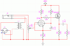
 I did som work on the schematic again
Attachments
I think I should read the radiotron designers hanbook again. Then I might find out why it isn't always used that way
The screen smoothing cap can be connected to ground if a cathode bypass cap is used (as in your circuit), because the cathode is at signal ground so it doesn't make any difference. However, if part or all of the cathode resistor is unbypassed, then the screen cap must be connected to cathode, so that the screen follows cathode voltage fluctuations with the signal.
I prototyped my mic preamp. It works, but it still needs some work done. The only thing I changed was a 220K anode resistor, I didn't have A 270K on stock. These are some readings:
Power supply voltage: 250V
Anode voltage= 76V
gain=100 measured with 0.1V input, 1KHz
There's very little noise and No hum at all. Now it sounds a bit on the "warm" side. Tomorrow I'll try fooling around with the cathode resistor. Maybe adding a resistor in series and bypassing it with a cap so I don't loose gain. Any thoughts?
G2/screen voltage? Very important.
That's from the high output impedance of the EF86 driving the high input capacitance of the directly coupled source follower i.e. gate to source, gate to drain. Not miller capacitance because of being in source follower mode. I have simmed it which shows a steep early HF roll-off starting around 10kHz.
Much better HF response can be had using a tube cathode follower. And also I think a HT of 400V is quite high and unnecessary for a mic-pre. 250-300V HT would be more desirable.
Wayne
Now it sounds a bit on the "warm" side.
That's from the high output impedance of the EF86 driving the high input capacitance of the directly coupled source follower i.e. gate to source, gate to drain. Not miller capacitance because of being in source follower mode. I have simmed it which shows a steep early HF roll-off starting around 10kHz.
Much better HF response can be had using a tube cathode follower. And also I think a HT of 400V is quite high and unnecessary for a mic-pre. 250-300V HT would be more desirable.
Wayne
I got the idea of using a mosfet from this page: http://www.geofex.com/Article_Folders/mosfet_folly/mosfetfolly.htm
Once again it has been proven that's it's better to bring out some datasheets and a calculator, than to trust some website.
I want to keep the tube count down (costs), so I will also look into some other ss solutions (other mosfet, bjt). If the tube follower proves to me to be better sounding, I'll use the tube.
The screen voltage is higher than the anode voltage, it's 85 volts.
The power supply voltage is 250V
Anode voltage= 76V
Back to the drawing board
Once again it has been proven that's it's better to bring out some datasheets and a calculator, than to trust some website.

I want to keep the tube count down (costs), so I will also look into some other ss solutions (other mosfet, bjt). If the tube follower proves to me to be better sounding, I'll use the tube.
The screen voltage is higher than the anode voltage, it's 85 volts.
The power supply voltage is 250V
Anode voltage= 76V
Back to the drawing board

>>Back to the drawing board  <<
<<
Increase the value of the screen dropping resistor until you get what's needed voltage wise.
An alternative to a screen dropping resistor is a Zener diode stack. Tightly regulated screen grid B+ in pentode circuits reduces distortion. If you increase the B+ rail voltage, which in turn increases the anode voltage, then you could use a VR75 gas diode to regulate the g2 B+.
 <<
<<Increase the value of the screen dropping resistor until you get what's needed voltage wise.
An alternative to a screen dropping resistor is a Zener diode stack. Tightly regulated screen grid B+ in pentode circuits reduces distortion. If you increase the B+ rail voltage, which in turn increases the anode voltage, then you could use a VR75 gas diode to regulate the g2 B+.
@ svokke
If you want that HF roll-off and the resulting 'warm' sound, by all means keep the mosfet! We're not talking a high quality phono-pre or line stage here!
Owww now! You got "ONE" tube already! A good 6SN7 or 6CG7/6FQ7, or a 6GU7 plus another tube socket won't set you back that much! And if you don't POP a bunch of MOSFET's in the process of building and testing (one slip of a probe and oops! s***!) Plus I'd bet the "all" tube mic-pre will sound better, IMHO.
I'm not preaching anti-sand state at you! If sand is what you want, by all means go for it! Now back to the topic.
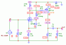
Here's a sim of your circuit I've done a few days ago. Now this is highly dependant of the models I've used for the sim, so in the real world the values of current and voltage will be different. But it will get you in the ball park.
Cheers
Wayne
If you want that HF roll-off and the resulting 'warm' sound, by all means keep the mosfet! We're not talking a high quality phono-pre or line stage here!
I want to keep the tube count down (costs), so I will also look into some other ss solutions (other mosfet, bjt). If the tube follower proves to me to be better sounding, I'll use the tube.
Owww now! You got "ONE" tube already! A good 6SN7 or 6CG7/6FQ7, or a 6GU7 plus another tube socket won't set you back that much!
I'm not preaching anti-sand state at you! If sand is what you want, by all means go for it! Now back to the topic.
Here's a sim of your circuit I've done a few days ago. Now this is highly dependant of the models I've used for the sim, so in the real world the values of current and voltage will be different. But it will get you in the ball park.
Cheers
Wayne
Attachments
Eli
I've read this: www.geofex.com/Article_Folders/mosfet_folly/mosfetfolly.htm
And I agree. But I think an EF86 configured as in this instance will have a much higher output impedance than any 12AX7, so there will be a reduction in HF response. The gate to source won't be of much consequence but the gate to drain will IMO as the drain is at AC ground. I and MC6 could be wrong or my MOSFET models are throwing it.
I've often thought of using MOSFET's and JFET's alongside tubes! One experiment involved a J-FET at the bottom position in a cascoded linestage. That's about as far as I've gotten mating the two, so far!
Cheers
Wayne
I know NADA about simulations. Having said that, I have my doubts. The I/P impedance of a MOSFET voltage follower is MANY MOhms. This circuit is DC coupled; so, there is no gate resistor to lower the I/P impedance. Is it possible that the significant gate capacitance of the FET is causing HF rolloff?
IRF820:
Vds = 25V
Vgs = 0V
Ciss = 350pf = Input capacitance
Coss = 54pf = Output capacitance
Crss = 9.6pf = Transfer capacitance
I'm lucky, I have a Japanese FET manual! Sure am glad I dropped 17 USD for this baby back in '92!
Input resistance should be in the giga-ohms. Even though the source follows the gate (that's what we're aiming for hopefuly!, same phase) the drain will not. Transfer capacitance. The 220R grid stopper will have little effect in this case compared to the hundreds of k output impedance (174k) of the EF86.
Ok in MC6 I added a 10pf cap from gate to drain of the MOSFET. HF -3dB response dropped to 19kHz.
Wayne
- Status
- This old topic is closed. If you want to reopen this topic, contact a moderator using the "Report Post" button.
- Home
- Amplifiers
- Tubes / Valves
- microphone preamp
