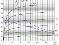
It's difficult to make a pentode into a triode load line except when you have curves at Vg1=0 and varying Vg2. And even then, you can oly derive the Vg1 = 0 curve. Fortunately, triode curves for the EL84 are easily available. Look at the Mullard data sheet, available at the ubiquitous and invaluable Frank's Electron Tube page.

Hi SY and All,
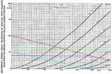
I found Mullard datasheet... yes there's drawing for triode... I also tried to draw with Plate Voltage 250V Plate Current 40mA at load 5k Ohm. Unfortunately i can't see max voltage since it off scale. the load line is on the red line while green line is max. plate current (65mA).
Now, Am I draw it correctly?
Attachments
Thanks for your Info SY...
If i set up circuit to follow the red line, what about the max current limit? I marked green line as Max current limit (65mA).
Does it mean that's a bad load line because already reach max current before bias get 0 Volt or I still can use it as long as i don't drive it near max current....?
Thank you for your explanation and others opinions are welcome too....
best regards
I wouldn't worry too much about the max current since your average current will be well below that. You might want to plot max dissipation on those curves to see if your loadline stays below it (on average).
Off the top of my head, 5K and 250V is pretty safe for an EL84- in my little amp, I'm running them with 300V in a push-pull circuit with 8K plate-to-plate. That corresponds to a 2K load single-ended, which is tougher than your load. My tubes seem to be perfectly happy.
Off the top of my head, 5K and 250V is pretty safe for an EL84- in my little amp, I'm running them with 300V in a push-pull circuit with 8K plate-to-plate. That corresponds to a 2K load single-ended, which is tougher than your load. My tubes seem to be perfectly happy.
Thank You SY....
Your word encouraging me to continue this project....
FYI my project is trying as many as topolagy using this babies...
But due to the famous trannys (Lundahl, Tamura, AN, Electra Print. etc) in my country are very expensive then i tried with local wound. I use big size (20-25 watt OT) in order to help Lo Freq and it appearently the high is helped by Direct Coupled Topology...
then Nightmare comes, the driver failed and burn all my tubes including rectifier. Then I start to think about how build a safe Direct Coupled.... I had been given some idea by some member this milis. It seem Thorsten "Monkey" idea is the safest Direct Coupled Topology. That's why I keep leaning about the design of single ended, to know is this topology can be adopted in SE-EL84... The next thing I hope that you would explain to me about how much different between choke load andresistive load...
But anyway I thank you very much for your help inthis milis which makes my knowledge better... thank you all
best regards
- Status
- This old topic is closed. If you want to reopen this topic, contact a moderator using the "Report Post" button.
- Home
- Amplifiers
- Tubes / Valves
- Tube Load Line