How long it will last
Hi all,
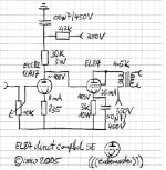
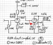
I built EL84 direct coupled michael "Tube Master". I like the sound very much (thank you tube master...)
But due to the driver is pushed harder (8mA) my friend said that this will shorter the tube life. And when driver die it will kill the output too since grid of output tube will recieve high voltage. my friend said if i played in normal listening for 3 hrs/day then the tube will last about a year....
is this true? is there anything i can do to prevent this.... at least is there anything i can do to make the output tubes don't die together with the driver...
rgds
Mas Penk
Hi all,
I built EL84 direct coupled michael "Tube Master". I like the sound very much (thank you tube master...)
But due to the driver is pushed harder (8mA) my friend said that this will shorter the tube life. And when driver die it will kill the output too since grid of output tube will recieve high voltage. my friend said if i played in normal listening for 3 hrs/day then the tube will last about a year....
is this true? is there anything i can do to prevent this.... at least is there anything i can do to make the output tubes don't die together with the driver...
rgds
Mas Penk
Attachments
Re: How long it will last
Hello Mas,
congratulations on finishing the project!
Don't worry about that at all. The typical rating of the ECC82 according to the Philips Datasheet is 10-12 mA. The maximum allowed cathode current is 20 mA so you are well within the limits. Depending on the model expect the tube to last for many years indeed! I have seen ECC82s which have been in service for more than 30 years.
Apart from that the tube normally does not fail instantly but will slowly go weak with less gain and a change in sound so you have plenty of time to notice. It is very rare for a preamp tube to fail completly, I have never seen this happen myself.
So don't worry and enjoy the music!
Best regards
Michael
Hello Mas,
congratulations on finishing the project!
Mas Penk said:But due to the driver is pushed harder (8mA) my friend said that this will shorter the tube life. And when driver die it will kill the output too since grid of output tube will recieve high voltage.
Don't worry about that at all. The typical rating of the ECC82 according to the Philips Datasheet is 10-12 mA. The maximum allowed cathode current is 20 mA so you are well within the limits. Depending on the model expect the tube to last for many years indeed! I have seen ECC82s which have been in service for more than 30 years.
Apart from that the tube normally does not fail instantly but will slowly go weak with less gain and a change in sound so you have plenty of time to notice. It is very rare for a preamp tube to fail completly, I have never seen this happen myself.
So don't worry and enjoy the music!
Best regards
Michael
Connect a reverse-biased diode between the grid and cathode of the output tube to protect it in case the driver goes out. In normal operation, the diode is an open circuit, but if there's a fault which tries to drive the grid positive, it will act as a clamp.
Hmmm, second time today I've given that advice.
Hmmm, second time today I've given that advice.
Guys I believe Mas Penk was talking about his output tubes; EL84
Sy is correct. I would use a 1N4007 from grid to cathode, the anode side of the diode connected to the grid and cathode to cathode. Say the filement burned out, went out, or some other fault condition like a bad tube socket, that diode will "protect" your output tube. It will shunt current from the grid to cathode and then to ground through the cathode resistor.
Also Me thinks Mas Penk may be worried that the 12AU7 may pull too much grid current from the EL84 during maxed out operation. Sy's suggestion will prevent that from happening. We don't want your amp to go into class "C" operation! joke! Well we would if we wanted a RF transmitter!
You may hear some very nasty asymentrical clipping if driven way past the operating point due to positive grid current. You would also hear it with the diode in place due to it clipping the positive going output of the driver, starting at about 550mV. Which means you've overdiven the EL84 as a result of the cathode not keeping up with the grid; grid going positive with respect to the cathode.
Whew! So as long as you don't push it that hard and use a protection diode, you're fine! Always use protection, son...yeah!
Wayne
is this true? is there anything i can do to prevent this.... at least is there anything i can do to make the output tubes don't die together with the driver...
Sy is correct. I would use a 1N4007 from grid to cathode, the anode side of the diode connected to the grid and cathode to cathode. Say the filement burned out, went out, or some other fault condition like a bad tube socket, that diode will "protect" your output tube. It will shunt current from the grid to cathode and then to ground through the cathode resistor.
Also Me thinks Mas Penk may be worried that the 12AU7 may pull too much grid current from the EL84 during maxed out operation. Sy's suggestion will prevent that from happening. We don't want your amp to go into class "C" operation! joke! Well we would if we wanted a RF transmitter!
You may hear some very nasty asymentrical clipping if driven way past the operating point due to positive grid current. You would also hear it with the diode in place due to it clipping the positive going output of the driver, starting at about 550mV. Which means you've overdiven the EL84 as a result of the cathode not keeping up with the grid; grid going positive with respect to the cathode.
Whew! So as long as you don't push it that hard and use a protection diode, you're fine! Always use protection, son...yeah!
Wayne
Don't know if it is of much use, but thought I would post it anyway.
http://www.glass-ware.com/tubecircuits/Tube_Line_Stage_Amplifier.html
http://www.glass-ware.com/tubecircuits/Tube_Line_Stage_Amplifier_3.html
Erik
http://www.glass-ware.com/tubecircuits/Tube_Line_Stage_Amplifier.html
http://www.glass-ware.com/tubecircuits/Tube_Line_Stage_Amplifier_3.html
Erik
Well, i think it worth to try....
This is my calculation :
1. when when the driver fails then voltage upper plate resistor (measured around 335 V) will draw current about 10mA. (335 / (30k (driver's plate resistor) + 3k (output cathode resistor))= ~10mA)
2. voltage around diode ((3k/33k)*335=10V)
3. difference between cathode and grid of output tube around 0.3 - 1.2V depend what kind of diode used.
but before i try it... i wanna know that my calculation is correct or not....
Hi...
I don't think the audio signal will pass through the diode since the cathode always be higher that grid. if you checked the first circuit i attached, the cathode voltage is around 109V while grid is around 100V (the output tube is biased at -9V). So there no way i send music signal to the cathode since cathode always 9V higher than the grid.
But i'm no expert here... maybe other exlplanation from more experienced person will make things more clear...
best regards
But still with the diode, the current in the EL84 will be very high if the driver fails. 
Another approach to avoid smelt down is to put a zener diode between ECC82's plate and ground. A proper zener will limit the maximum voltage into EL84's grid in case of driver failure and will not effect the signal.
Another approach to avoid smelt down is to put a zener diode between ECC82's plate and ground. A proper zener will limit the maximum voltage into EL84's grid in case of driver failure and will not effect the signal.
I don't know if the output tube will draws high current because based on john broskie said "What does the diode do in this circuit?"
This diode does not do anything during the normal operation of the circuit. It can't; as the diode is so placed that the cathode would have to be at some lower voltage than is the grid, which under normal operation does not happen. The tube (being a depletion mode device) conducts current in spite of the grid being negative relative to the cathode, which is the basis for cathode biasing, or as it is sometimes called "auto biasing." If the grid were to become positive relative to the cathode, however, the diode would conduct and the greatest voltage difference between the grid and cathode would equal the voltage drop across the diode, which is usually between 0.3 to 1.2 volts. A situation that could happen if the grid were driven with an excessively large input voltage or if the B+ voltage were established and the tube remained too cold to emit electrons. The latter situation is what usually happens every time a fast solid-state power supply comes up to full voltage before the tube's cathode has had time to heat up sufficiently to conduct current. In this circuit at startup, without the diode, thegrid of the Cathode Follower would be at the B+ voltage and its cathode at ground potential, which might damage the tube by exposing it to cathode stripping. (Large positive grid to cathode voltages can cause the grid to exert so great an electrostatic pull on the cathode that portions of the cathode are literally stripped away and fly onto the plate, thus damaging the tube.) At only ten cents, the addition of a diode makes a great bargain.
This diode does not do anything during the normal operation of the circuit. It can't; as the diode is so placed that the cathode would have to be at some lower voltage than is the grid, which under normal operation does not happen. The tube (being a depletion mode device) conducts current in spite of the grid being negative relative to the cathode, which is the basis for cathode biasing, or as it is sometimes called "auto biasing." If the grid were to become positive relative to the cathode, however, the diode would conduct and the greatest voltage difference between the grid and cathode would equal the voltage drop across the diode, which is usually between 0.3 to 1.2 volts. A situation that could happen if the grid were driven with an excessively large input voltage or if the B+ voltage were established and the tube remained too cold to emit electrons. The latter situation is what usually happens every time a fast solid-state power supply comes up to full voltage before the tube's cathode has had time to heat up sufficiently to conduct current. In this circuit at startup, without the diode, thegrid of the Cathode Follower would be at the B+ voltage and its cathode at ground potential, which might damage the tube by exposing it to cathode stripping. (Large positive grid to cathode voltages can cause the grid to exert so great an electrostatic pull on the cathode that portions of the cathode are literally stripped away and fly onto the plate, thus damaging the tube.) At only ten cents, the addition of a diode makes a great bargain.
You are probably right.
When the diode conducts the B+ voltage will be divided by the 30k driver plate resistor and the 3k cathode resistor, and the voltage on the grid will not be higher than ca B+/11 (plus extra voltage drop over the cathode resitor due to cathode current)
Yes, a diode will do the trick!
When the diode conducts the B+ voltage will be divided by the 30k driver plate resistor and the 3k cathode resistor, and the voltage on the grid will not be higher than ca B+/11 (plus extra voltage drop over the cathode resitor due to cathode current)
Yes, a diode will do the trick!
Any quality NOS 12AU7 will last at least 5000 hours or longer in your circuit. Expensive, but Amperex 6085 that draws a few more millamperes drops-in the 12AU7 socket & will last even longer than a 12AU7. Perhaps 20000 hours. The Amperex 6085 is the best 12AU7 type I ever heard. Brimar 13D5 is close in sonic performance.
- Status
- This old topic is closed. If you want to reopen this topic, contact a moderator using the "Report Post" button.
- Home
- Amplifiers
- Tubes / Valves
- How long it will last?