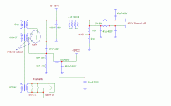
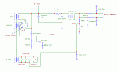
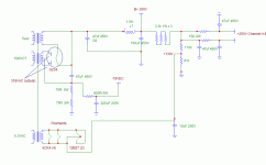
I had a choke that I ordered by mistake, so I thought I'd play with it in a cap input supply. When I modeled it in PSUD, it showed a big reduction in B+ ripple with only a loss of about 10V. So I plugged it in per the following schematics. When I did the various measurements, the voltages all checked out as predicted, but my output hum went from less than 1mv to about 4mv. At first I thought it was the clip leads strung around, so I just removed the choke and extra cap and completed the circuit with the leads. Hum dropped back to <1mv, even moving the leads around. Could the choke be influencing the power transformer?
Edit: Thinking about it, I didn't ground the choke chassis. Could this be a problem?
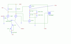
Amp:
Edit: Thinking about it, I didn't ground the choke chassis. Could this be a problem?
Amp:
Attachments
Hi Cris,
Yes, the supply was loaded. I just power up the amp same as for the non-choke supply. No signal connection, but all systems go. I don't think orientation was the problem, as it was outside the amp and at least 10 cm away from the output transformers. Also, moving the choke around had no effect. Is it loading my ground in some way?
Sheldon
hi
did you check the orientation of the choke?
these things have a magnetic field around them, and unsurprisingly, it can couple with the output transformer. Try having the magentic cores at 90 degrees to each other. this is normal practice when building amps.
Also, earth the case of the choke, or the laminations, this too keeps hum down.
Hope that this helps.
kind regards
bill
According to your schematic, it is not a Choke Input LC filter. It is just a C-L-C PI filter. The 350V B+ should be tapped after the choke.
If you don't have hum problem with the original circuit, the hum probably caused by the magnetic flux generated from the choke and coupled to the OPT.
Johnny
If you don't have hum problem with the original circuit, the hum probably caused by the magnetic flux generated from the choke and coupled to the OPT.
Johnny
I noticed that the original power supply has a 100uF input capacitor. The second power supply has a 47uF input capacitor.
That would explain the higher hum level. I would move the B+ connection to the output side of the choke.
Also. 100uF is too much capacitance. Most tubes are rated for 40uF to 60uF maximum. 100uF will shorten the life of your rectifier tube.
That would explain the higher hum level. I would move the B+ connection to the output side of the choke.
Also. 100uF is too much capacitance. Most tubes are rated for 40uF to 60uF maximum. 100uF will shorten the life of your rectifier tube.
The GZ34/5AR4 should not operate into more capacitance than 60uF.
This is a link to the information.
http://www.mif.pg.gda.pl/homepages/frank/sheets/010/g/GZ34.pdf
This is a link to the information.
http://www.mif.pg.gda.pl/homepages/frank/sheets/010/g/GZ34.pdf
You guys have been active while I was away for the day. Thanks for the time and interest.
Anyway:
My schematic drawing is wrong. The B+ is taken after the choke, I just forgot to change that. Sorry for the confusion.
The choke is rated for 200mA and I'm drawing about 160.
I don't think that coupling is the problem, as I just connected up the circuit with clip leads and the choke is located a fair distance from the OPT's - my first post said 10cm but it was probably more like 25cm. Also, both channels are affected the same way, even though one is further from the choke.
I know that the input cap is large. I just built this amp from a schematic in the Fi primer, by J.C. Morrison. He spec'd a 5U4GB, but I went with the GZ34 to get the proper voltage from my power transformer. So far no problems. We'll see what life I get from the tube. Actually, that part of the reason I wanted to try the choke, so I could use a smaller cap after the rectifier.
I'll play around a little more and see what I find.
Sheldon
Correct Schematic:
Attachments
Hi Sheldon,
Did you realize the 5U4 is only rated for 40uF maximum for a capacitor input filter? RCA RC-30.
Some people need to read the manual (J.C. Morrison for one). Most later designers seem to be ignorant of this. Anyhow, it won't explode yet, but it's wrong. Wrong like never changing the oil in your car. You need to add series resistance to keep the peak current (hot switching) down if you want to use values above 40uF.
-Chris
Hmm, so this is interesting. I went back and checked again, moving stuff around, etc. Same result. This time, I measured the ripple at several points. I did this by using my DMM and a 0.1uf cap in series with the probe.
With the original schematic, 100uf cap input, I get about 0.5v ripple.
With the choke in place, I get about 5v ripple and after the choke about 2.5v.
That could certainly explain the increase in residual AC. But why would the ripple be greater with the choke and extra cap in line? That's the opposite of what the PSUD simulation suggests, although the predicted voltage changes were spot on.
Sheldon
BTW the choke is a Hammond 156R
anatech said:Hi Sheldon,
Did you realize the 5U4 is only rated for 40uF maximum for a capacitor input filter? RCA RC-30.
Some people need to read the manual (J.C. Morrison for one). Most later designers seem to be ignorant of this. Anyhow, it won't explode yet, but it's wrong. Wrong like never changing the oil in your car. You need to add series resistance to keep the peak current (hot switching) down if you want to use values above 40uF.
-Chris
Yes I know. What can I say, sometimes I like living on the edge. But seriously, that's why I was fooling with it, to be nicer to the the rectifier. It does sound very nice.
Sheldon
Dr Berry's point is important, although the exact procedure is a little more complex than to just stay below a certain value of input capacitor. The important (current limiting) parameter is the total impedance in serie with a rectifier anode. My tube manual gives that as 160 ohm for the GZ34. This should consist of both the capacitor impedance plus the transformer winding impedance plus any series resistor that may be used. (The latter is used in some circuits rather than limit the capacitor and so increase ripple.)
As the charging of the capacitor in a C-input filter takes place for less than a half cycle, this matter is a little more complex than just working on 50 or 100 Hz impedances - for exact calculation the whole of the filter plus the current drawn is significant, but also tedious and one gets away with practical measurements. If you can do it safely, maximum current at a rectifier plate is best determined with an oscilloscope. Your DVM reading (mostly rms or average current) can be misleading. Although there is no direct relation between power transformer winding impedance and resistance, can you give the d.c. resistance of one half of your high voltage winding?
But after all this theory, your findings are still mystifying. You find 0.5V ripple without the choke and 5V with it? At the same point? If I do not misunderstand you, an inspection by scope would be interesting. A last thought: One does not usually decrease the value of a filter's output capacitor just because the ripple is OK; it also has to do with low power supply impedance to signal. Too low a value could cause l.f. instability (motor-boating), although I think you are still safe in that department.
Please keep us posted; this is something too often overlooked, as indicated by other contributors.
Johan Potgieter said:But after all this theory, your findings are still mystifying. You find 0.5V ripple without the choke and 5V with it? At the same point?
Thanks. Give me a while to digest the whole of this. I'm heading to dinner now. But in answer to the above; yup.
The transformer is a Hammond 272 HX, 4.4 ohms primary side, 38/39 secondary.
Sheldon
Oh, be sure and note the resistors on the center tap that I'm sucking the electrons through.
Ok,
If we ignore the 47uf cap in the ct circuit (cause I'm not sure how make a model equivalent in PSUD), the 150 ohms are simply in series with the input cap. And in PSUD that gives the correct voltages, but the ripple is about 5V. If I simply add the 47 to get a total of 147uf, the voltage is essentially the same (360) but the ripple drops to about 3v. If I put the 47uf in parallel (with a very low value resistor just to avoid illegal combinations) but make its internal resistance 150ohms (because PSUD won't let me put a resistor in series with the cap) I model about the actual measured ripple (approx. 0.5v), but the voltage is about 290, lower than actual.
So??? And I still don't understand why the choke would increase the ripple.
BTW, with the 150hms in series, I'm within all the current and voltage specs of the rectifier after a couple of cycles. Those first cycles in real life wouldn't be that high either due to the slow start-up. Don't know if that meets the above criterion.
Sheldon
- Status
- This old topic is closed. If you want to reopen this topic, contact a moderator using the "Report Post" button.
- Home
- Amplifiers
- Tubes / Valves
- Choke induced Hum


