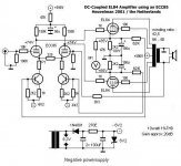
EW published several d.c. coupled EL84 amps designed by Kees Heuvelman and Wim de Haan in January 2001. Wim has a link on his page to the design. Here's the link:
http://www.wdehaan.demon.nl/tubeamps/el84dc/index.html
Here's a first cut at a pcb
i'm open to suggestions -- i am sure there are probably some glithces in the above.
will furnish the Gerber files to anyone who asks -- I am only going to burn one board for my own use.
http://www.wdehaan.demon.nl/tubeamps/el84dc/index.html
Here's a first cut at a pcb
An externally hosted image should be here but it was not working when we last tested it.
i'm open to suggestions -- i am sure there are probably some glithces in the above.
will furnish the Gerber files to anyone who asks -- I am only going to burn one board for my own use.
Hi Jack,
At first sight:
The cathode resistors dissipate a lot of heat. I think a heatsinked version would be a better choice. Anyway, the footprints look too small.
The heaters' tracks for the ELs might be thicker and routed "one on top of another" with the same current flow direction.
Regards,
Milan
P.S. Nice article in AudioXpress.
moamps said:Hi Jack,
At first sight:
The cathode resistors dissipate a lot of heat. I think a heatsinked version would be a better choice. Anyway, the footprints look too small.
Yes, they should dissipate ~ 10 W.
The tracks for the heaterers are mostly 60 mils -- will have to give this some thought -- for the boards I do myself I like to have as much as possible on the bottom layer.
The EL84 DC amp is going to power my St. Emillion Horns (in a modified wooden Bordeaux wine-box.)
Thanks for the compliment -- National did all the heavy lifting, however.
moamps said:The heaters' tracks
Best not to put heater wires on the board at all. Use a twisted pair and run it as far from the board as you can and then just reach up to connect to the heater pins.
dave
This is version 4 -- with the ECC88 current source -- but I am going to outboard the -150V/+206V supply -- so both halves of the ECC88 are used for two amps on one board.kopite said:Hello Jack, nice job.
Which version of the ECC85 is it? I think Wim goes on to say that the version with the better ccs doesn't need feedback. Is yours it?
Thanks,
Phil.
Dave -- I agree, the 60 mil trace width will poop out under the pressure of 7 tubes in parallel.
OK, here's a 3D view -- I changed the resistors to the TO-220 style (Ohmite or Caddock, non-inductive) with heat sink -- they now take up a lot more space. I also removed the heater traces. Note that I try to take the grounds to the center of the board. I also use a "via" for connecting the top-layer traces -- helps when you are DIY'ing a board to have the darned hole there.
here's the PCB:
An externally hosted image should be here but it was not working when we last tested it.
here's the PCB:
An externally hosted image should be here but it was not working when we last tested it.
planet10 said:A very tempting design with all the ECC85s & EL84s i'm sitting on...
dave
i hate to think of pulling the shards out ---

")
jackinnj said:
This is version 4 -- with the ECC88 current source -- but I am going to outboard the -150V/+206V supply -- so both halves of the ECC88 are used for two amps on one board.
Dave -- I agree, the 60 mil trace width will poop out under the pressure of 7 tubes in parallel.
Hi
I'd sugest to connect both EL84 cathodes to each other, and leave the decoupling caps out.
This requires tightly matched valves and good DC balance from the driver.
best
Link to article here: http://www.wimdehaan.nl/downloads/dccoupledamp.pdf
FWIW other comments not withstanding I would build the circuit as described in the article, and then modify if so inclined. High quality cathode bypass caps are a must however..
The meter is used to establish overall DC balance in the amplifier. Meter is a 50uA-0-50uA type as mentioned in the early paragraphs of the article.
Last edited:
The article is based on one assumption: (quote of the author)
" I believe that coupling capacitors have a major influence on the overall sound quality of an amplifier."
Have we so far got any evidence that this would be the case ?
I have not seen such.
That could be an interesting and distinctive project to build, but the test results published at the article do not show any excellence over normal construction with coupling capacitors.
The article is based on one assumption: (quote of the author)
" I believe that coupling capacitors have a major influence on the overall sound quality of an amplifier."
Have we so far got any evidence that this would be the case ?
I have not seen such.
That could be an interesting and distinctive project to build, but the test results published at the article do not show any excellence over normal construction with coupling capacitors.
Actually I believe this based on long experience designing audio gear, but I also believe it is much easier to find an electrically blameless and good sounding film coupling cap than it is to find an equally good sounding cathode bypass cap regardless of cost. (By good sounding I mean transparent, and audibly artifact free. And yes I have done some single blind testing with coupling caps and a small listening panel. The result of that is that I now use mostly teflon/foil coupling caps. The Russian FT-3 is good and not too expensive a place to start. I use TFTs and Vcaps mostly.)
Last edited:
I got rid of a gain stage (and thus a coupling cap) in my power amp because my preamp has enough gain, and that really cleared things up. So much so I got very interested in dc coupling. But no 'scientific evidence'..
(And I started thinking..)
Everyone will agree looking through an open window gives a better view then through glass. You can debate which sort of glass is the clearest, but no glass is always better..
(And I started thinking..)
Everyone will agree looking through an open window gives a better view then through glass. You can debate which sort of glass is the clearest, but no glass is always better..
- Status
- This old topic is closed. If you want to reopen this topic, contact a moderator using the "Report Post" button.
- Home
- Amplifiers
- Tubes / Valves
- Wim's DC EL84 amp