Hello!
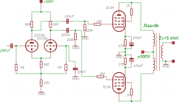
I have built the attached circuit. I think, that's very simple, common.
I have seen many many EL84 push-pull schematics, and all of them was working from about 300V supply. Almost all of them could deliver about 10W.
But my circuit delivers only 5W undistorted. Why?
What did I wrong?")
Oh, another question!
The amplifier's frequency-response starts to fall at about 15kHz. Why? If I apply a feedback from the output trafo, to the LTP, then will this falling at 15kHz go to a higher frequency?
I have built the attached circuit. I think, that's very simple, common.
I have seen many many EL84 push-pull schematics, and all of them was working from about 300V supply. Almost all of them could deliver about 10W.
But my circuit delivers only 5W undistorted. Why?
What did I wrong?
Oh, another question!
The amplifier's frequency-response starts to fall at about 15kHz. Why? If I apply a feedback from the output trafo, to the LTP, then will this falling at 15kHz go to a higher frequency?
Attachments
Your amplifier gives exactly the output power that is expected by EL84 push-pull in triode mode, see here http://www.triodeel.com/6bq5p3.gif
For higher power you need to connect the tubes as pentodes or as Ultralinear, in class AB pentode you can get up to 17W at 300V see here http://www.triodeel.com/6bq5p2.gif
Note that output power in datasheets are given as the output power from the tubes, the losses in the output transformer are not considered so in reality you would expect a bit less after the output transformer.
Regarding the fall at higher frequency it is probably due to the quality of the output transformer, feedback will improve the frequency response but too much feedback increase the risk of oscillation.
Regards Hans
I searched the g00000gle, and I modified my circuit to this:
http://sziget.mine.nu/~danko/aramkor/tube-amp/Screenshot-223.png
After I powered up, the output tubes were entirelly glowing!)
http://sziget.mine.nu/~danko/aramkor/tube-amp/dscn7916.jpg
http://sziget.mine.nu/~danko/aramkor/tube-amp/dscn7917.jpg
http://sziget.mine.nu/~danko/aramkor/tube-amp/dscn7918.jpg
Theese tubes are my test-tubes, they are some old EL84 tubes. I tested the circuit with my /almost/ brand new 6P14P tubes, they were also glowing.
I tried to modify the resistors, but there was no change
http://sziget.mine.nu/~danko/aramkor/tube-amp/Screenshot-223.png
After I powered up, the output tubes were entirelly glowing!
)http://sziget.mine.nu/~danko/aramkor/tube-amp/dscn7916.jpg
http://sziget.mine.nu/~danko/aramkor/tube-amp/dscn7917.jpg
http://sziget.mine.nu/~danko/aramkor/tube-amp/dscn7918.jpg
Theese tubes are my test-tubes, they are some old EL84 tubes. I tested the circuit with my /almost/ brand new 6P14P tubes, they were also glowing.
I tried to modify the resistors, but there was no change

How loud is loud?
Danke,
To get a percieved doubling in loudness you need to increase the acoustic power by 10 times... Given typical loudspeaker compression that means up to 15 times the electrical power or 75 Watts.
Going from 5W to 10W output is not really noticeble - particularly when the harder clipping of ultralinear or pentode mode is taken into account...
In other words you are not going to make the sound louder by changing this circuit - and you stand every chance of making it sound worse...
Still it's a good learning experience - so don't stop, just don't expect too much.
good luck
James
I played a little, with the grid-resistors. I tried 470R, 2k2, 22k...
With 22k the grid voltage was about 190-200V, and the plate was glowing only a little bit. But still glowing ...
The current state is: The screen-grid resistors are 22k, the B+ is 315V(loaded) and on the 150 Ohm cathode resistor, there's 21V.
On the screen, there's 160V.
And the speaker is hummming.
You might have a problem with the output tubes' cathode resistor and/or bypass cap. First, check to see that the cap is OK and not leaking. Second, double-check that your cathode resistance is what you had planned. Maybe one or the other is out of spec?
You might also have a massive oscillation. Have you looked at the output with a scope?
You might also have a massive oscillation. Have you looked at the output with a scope?
21V across the 150 cathode resistor implies a combined plate current of about 140mA which is way beyond what you should be using. These tubes can dissipate about 12W max and you are asking them to dissipate over 20W each, no wonder they glow. Something on the order of 60 - 70mA total cathode current would be about right - Try changing that 150 ohm resistor to about 250 - 300 ohms and see how things go.
I would configure for triode connection as it will sound cleaner, pentode connection should give you about 10 - 15W, but this is 3 - 5dB and it won't sound that much louder. To get it to sound twice as loud acoustically would require 10 times the power.
I have a somewhat similar amplifier with 7189 and about 400V plate voltage which produces a room filling 7 1/2W per channel
Kevin
There is another permutation that can be used......try common resistor in o/p stage (cathodes strapped together)
Use 150R common res; keep cathode decoupling cap. (300V B+) G2 strapped to anode.
THD will be around 1% depending on o/p stage matching. With triodes neither the ouput power nor thd will depend on the load resistance between 8-10Kohms.
OMO.....EL34's will give better power i.e 14W in triode p-p with B+400V.
richj
Giaime said:I think that 150ohm is right for a COMMON resistor, not just one for tube.
That's what he's using, 150 ohms as a common resistor. So... either there's something broken (e.g., coupling cap, wiring mistake) or his output tubes are wildly out of spec.


Hi!
I don't really know, what's wrong in this amp (on the breadboard), but it doesn't matter so much.
BTW, i'm made thoose pictures with two used tubes, but after that I changed them to new 6P14P tubes, and they were also glowing.
I works, it sounds, so I can continue experimenting on the amplifier.
I couldn't increase the output power, but I learned some things, and this is the porpuse of this amp!
Thank you all your help!
There are a number things to do ...
Most paramount thing with Hi-Fi pentodes is to REGULATE the screen voltage...this is VREY critical for linearity....
I would not use anything bigger than 1K for the screen grid resistors.... ALso regarding the HUM, make sure the screens are well decoupled to ground... You can elect to use a LC filter for the screens... Figure a 10H inductor and a 100uF cap to feed the both screens should be fine.....
Or use a voltage reg for the screens...but that would make the circuit very busy...
Chris
- Status
- This old topic is closed. If you want to reopen this topic, contact a moderator using the "Report Post" button.
- Home
- Amplifiers
- Tubes / Valves
- EL84-PP - Why just 5W?