Hello!
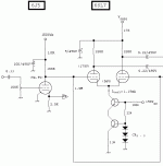
I have built this schematic:
On the schematic, there's 6SL7GT, but I used ECC85.
How can I calculate the voltage-gain of this stage?
Thanks in advance!
I have built this schematic:
An externally hosted image should be here but it was not working when we last tested it.
On the schematic, there's 6SL7GT, but I used ECC85.
How can I calculate the voltage-gain of this stage?
Thanks in advance!
SY said:The gain will be one-half that of the same circuit in grounded cathode.
Gain = muRp/2(Rp + rp), where Rp is the plate load resistor and rp is the plate resistance.
WOW! That is the most concise explaination of LTP gain calculation that I have ever heard. Good one!

There are a lot of good current source circuits floating around. Morgan Jones shows both bipolar and tube versions in "Valve Amplifiers." Gary Pimm has some more exotic examples on his web site. In the one long tailed pair amp I have at the moment (a rebuilt Eico HF87), I used a pretty simple cascode bipolar sink. The performance is excellent and it cost only a couple of dollars in parts.
If it's possible for you to use a small negative supply (say, -12V or so), you can greatly simplify your circuit and improve the balance by using a CCS tail.
If it's possible for you to use a small negative supply (say, -12V or so), you can greatly simplify your circuit and improve the balance by using a CCS tail.
As a side note, if you use the tail resistor instead of a CCS, don't forget that the sum of the 2 tube's current across the tail will eat your voltage at the plates down by it's value. It's an obvious mistake that I made once and plotted my loadlines about 60v too high, had quite a surprise when I built the thing up and tested it.
Why do people mostly use semiconductor CCS, and not tube-CCS? I have seen many tube-amplifier schematics, but just a few of them use tube based constant current source. Is it only, becouse of a MJE340, or BC546 is far more cheaper than a tube?
No, that's not the reason. A VT CCS requires a large, negative PS applied to the cathode of the CCS tube. Here is part of a design I'm working on (see attached). Given the voltages, the solid state CCS requires no additional power supply. To substitute a pentode for the cascoded transistors, you'd need a negative supply of, let's say -150V. If you already have such a supply, for fixed bias, then it's NBD. If you don't, then it's an extra complication that can easily be avoided.
Attachments
Danko said:Why do people mostly use semiconductor CCS, and not tube-CCS? I have seen many tube-amplifier schematics, but just a few of them use tube based constant current source. Is it only, becouse of a MJE340, or BC546 is far more cheaper than a tube?
A tube CCS will require a much larger voltage drop, a separate set of heater supplies, and for all of that will not give any better performance than a couple of bipolars. Often worse.
For all of that, some people love 'em and use 'em.
For all of that, some people love 'em and use 'em.
I do! I haven't had a happy time trying to mix SS with vacuum devices (except for SS rectifiers, of course).
I've found a 6AU6 pentode to be easy to use and effective as a CCS, in the tail of a 6SL7 LTP which has its grounded grid at true ground (0v). My negative rail is -110v. I make sure the heater of the 6AU6 is at a safe voltage that doesn't exceed the rated heater-cathode voltage limit 0f 100v.
Current per triode in the LTP is 0.8mA, which means the plate current of the 6AU6 is 1.6mA. Voltage from 6AU6 plate to cathode is 112v, screen to cathode is 95v. If you look at the 6AU6 plate curves for screen voltage ~100v, you will see that they are very flat for such a low current. The plate current appears to be constant within 0.01%. For more current, e.g. as a CCS for a 6SN7 LTP, a negative rail of 150v would be preferable.
Danko said:
How can I calculate the voltage-gain of this stage?
Thanks in advance!
I dug up these "rule of thumb" quick and dirty calculations from my archives. I think they were posted by Steve Bench on a forum somewhere:
"Differential amplifier (phase splitter etc) made from a 12AX7.
The plate load resistors are 150k each, and the next stage grid resistors are 220k. The cathodes are tied together and fed from a 2 mA current source.
What is the gain from either input to either output?
Solution: Effective Plate Resistance = 71k (plate resistance for these bias conditions) paralleled by 150k, paralleled by 220k or about 39k.
Effective cathode resistance. The current source is assumed to have a very high resistance, so may be neglected. Each cathode is "looking at" the other cathode. The gm under these bias conditions is about 1400 umhos (710 ohms). Therefore the cathode resistance is 710 + 710 or about 1420 ohms.
Stage gain = 39000/1420 = 27.5. Note that the differential gain (one input to both outputs) is double this (55), since equal and opposite output is provided by each plate.
This method also works for sand state devices as well."
- Status
- This old topic is closed. If you want to reopen this topic, contact a moderator using the "Report Post" button.
- Home
- Amplifiers
- Tubes / Valves
- LongTailedPair gain -> how to calculate?