Does anyone know of a data sheet comparing various tube rectifiers? So far, everyone I've found has an output voltage around 380 (assuming a high enough input), is this typical or are there other types with less or more voltage loss?
This is my first foray off a SS PSU design.
Thanks in advance for any help.
PB
This is my first foray off a SS PSU design.
Thanks in advance for any help.
PB
PSUD2
The PSUD2 program is the standard power supply sim for the DIY'er.
http://www.duncanamps.com/psud2/index.html
I routinely get within 0.5V of the predicted value with it. The key is measuring the DCR of your power transformer primary + secondary, and your line and off-load voltages. You then enter these into the program. It's a great tool.
Joel
Here's something else that will come in handy for this: Rectifier Applications Handbook
Thanks for the advice everyone, I downloaded the PSU designer and entered my prototype. I cannot figure out how to present the PSUD data here, however, I'm using a 250VCT transformer, 6CA4 rectifier, a C filter section at 100uF followed by an LC section at 20H/100uF supplying a load at 5K.
I meter the unloaded output of this at 385VDC which seems right inline with the 6CA4 datasheet.
However, when I run the simulator I get dire warnings about current limits and the final curve shows an output voltage of 600V !
Any ideas what I'm doing wrong?
Thanks in advance - PB
I meter the unloaded output of this at 385VDC which seems right inline with the 6CA4 datasheet.
However, when I run the simulator I get dire warnings about current limits and the final curve shows an output voltage of 600V !
Any ideas what I'm doing wrong?
Thanks in advance - PB
The 6CA4 is a GOOD tube. What you've built is proof. 100 muF. in the 1st filter cap. position is TOO big and exceeds the limits given in the data sheet. That you don't get arcing over (VERY BAD) at start up is a matter of luck. When using vacuum rectifiers, the 1st cap. in a CLC filter needs to be kept relatively small. Some tubes can tolerate only 4 muF. max. The 6CA4 is quite tolerant of capacitance for a vacuum rectifier, but it should not be over stressed. 20 muF. in the 1st position is GOOD, as it will keep the rail voltage up, without exceeding published limits. The choke protects both the rectifier and the power trafo (I^2R heating) from the 2nd filter cap. Piling up the energy storage in the 2nd position is OK.
"100uF is too big???"
Yes it is. Unlike solid state, you're dealing with high voltage, low current devices. A VT power diode doesn't have the ability to source the charging current a 100uF filter capacitor will demand. Back in the bad ol' days, some cheap equipment did have filter capacitors that big. This would overly stress the power diodes, however, it was assumed that you could just hop on down to the corner 7 - 11 and get a new one, and hope that the untech savvy customer wouldn't notice that his PS diodes were going bad too soon.
Since VTs aren't so easy to get, it pays to work them within the specs. Can't do that running them into such big filter capacitors.
Either go solid state, or use a ripple filter to clean up the AC mess.
Jay said:Miles Prower, thanks for the explanation. Now I know why my tube amps used small capsI was thinking about my pre-amp supply
Use a small cap for the first cap after the rectifier tube. Then use progressively larger caps through the filter section.
Using a 5U4-G with a max cap value of 40uF I built a filter section using 5U4-G -> 40uF -> choke -> 55uF -> resistor -> 80uF. The VT rectifier seems perfectly happy with this arrangement and there is sufficient current reserve.
Thanks all, this is great stuff. I think PSU design looks simple but is anything but.
What value would you recommend for the 1st cap? Is there an altogether better way of filtering here?
One more question on PSUD2; is CT transformer voltage rated to center or between the outputs (250-0-250 would be a 250V or 500V)?
Thanks again.
PB
What value would you recommend for the 1st cap? Is there an altogether better way of filtering here?
One more question on PSUD2; is CT transformer voltage rated to center or between the outputs (250-0-250 would be a 250V or 500V)?
Thanks again.
PB
philipbarrett said:Thanks all, this is great stuff. I think PSU design looks simple but is anything but.
What value would you recommend for the 1st cap? Is there an altogether better way of filtering here?
One more question on PSUD2; is CT transformer voltage rated to center or between the outputs (250-0-250 would be a 250V or 500V)?
Thanks again.
PB
According to the data sheet the max cap value for a cap input filter is 50uF.
In PSUDII the voltage is from secondary to CT, that is if your trafo is rated at 250-0-250 then use a value of 250 in PSUD.
Miles Prower said:Here's something else that will come in handy for this: Rectifier Applications Handbook
thanks a lot!
regards, opik
I think 100uF is not big for a pre-amp is it?
frank"s ultimate tube amps uses big caps:
12bh7a_srpp
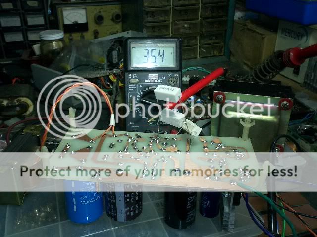
350volt psu
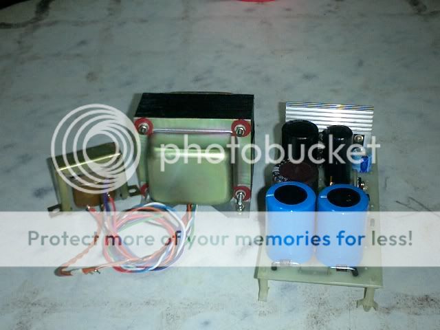
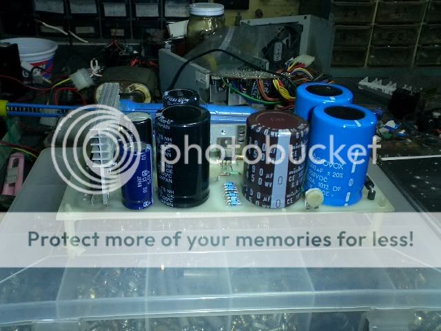
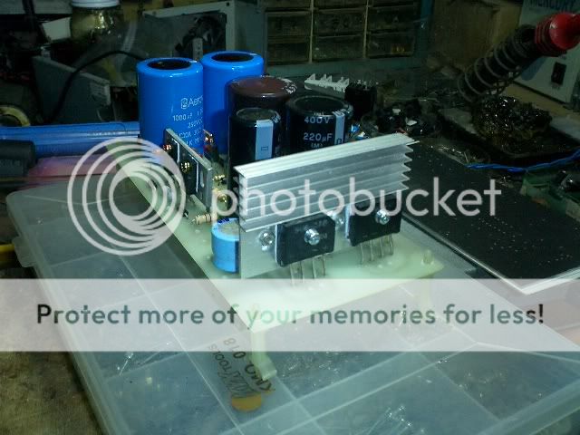
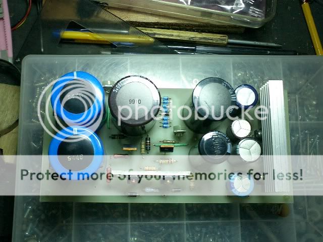
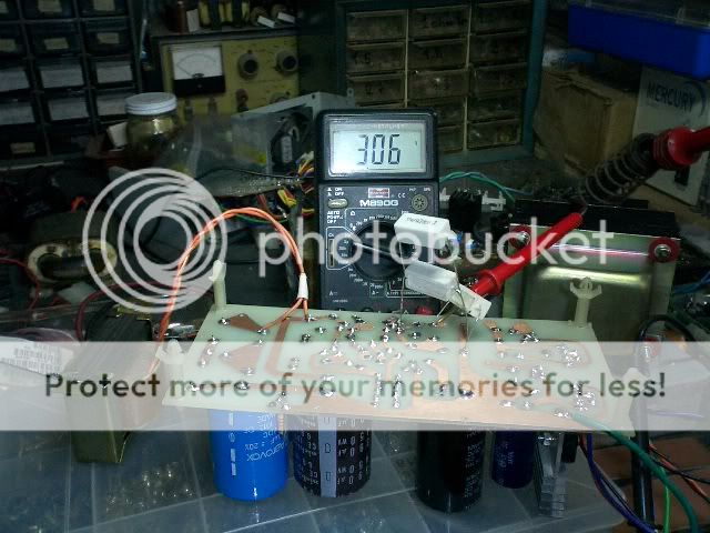
i made a psu using ss parts shown in my post above. it is a voltage doubler using mr4100 rectifers, large caps, and transistor series pass element.
Re: "frank's ultimate tube preamp uses big caps..."
fedgrove must have felt that big transformers and ss bridge provides for better regulation! very desireable for srpp amps.
costs aside, makes a lot of sense to me.
Joel said:Yes, but it also has a 1A power transformer, and a solid state bridge rectifier.
fedgrove must have felt that big transformers and ss bridge provides for better regulation! very desireable for srpp amps.
costs aside, makes a lot of sense to me.
- Status
- This old topic is closed. If you want to reopen this topic, contact a moderator using the "Report Post" button.
- Home
- Amplifiers
- Tubes / Valves
- Tube PSU Question