Hi,
at the moment I'm playing around with Duncanamps PSUD in order to try out some ideas for a tube based PS for the PP1C...
One main question to me is: How much ripple on the B+ rail is acceptable without hum problems? Searched the forum but found not much about it...
What about the negative rail for the tube CCS? Is the CCS more sensitive against ripple than the amp? How much ripple can one allow here?
Greetings
Andreas
A good CCS gives outstanding power supply rejection, as long as its reference is quiet. Push-pull circuitry also has excellent power supply rejection.
To determine what is acceptable, start by defining what your desired noise is for the amplifier, then start working backward to see how much ripple for each stage is allowable to achieve that goal.
To determine what is acceptable, start by defining what your desired noise is for the amplifier, then start working backward to see how much ripple for each stage is allowable to achieve that goal.
...thanks for your fast reply  , but I'm afraid that I'm unable to work my way back as you suggest... I'm still a total tube newbie...
Tried to simulate the original PP1C PS in PSUD and came to about 10mV ripple on the B+ rail...
About the CCS, the "standard" layouts for tube based CCS I found in the forum generate the reference from their supply voltage, does this mean I have to clean the negative rail up completely, or is it possible to filter the reference separately, lets say by a sufficiently big cap?
Greetings,
Andreas
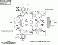
It ist going to be a EL34 PP amplifier, schematics see below...
I think for the B+ rail, I'll try to reach the values reached with the original supply in PSUD... Concerning the CCS i hope for more answers...
kmtang, you suggest a C-L-C-L-C filter, i thought about a L-C-L-C filter chain, as I read somewhere that tube rectification and big input caps in the filter chain aren't so good... What do you think?
Greetings
Andreas
Attachments
Hi Andreas,
For EL34 PP amp, it just need C-L-C filter for power supply. The push-pull configuration will cancel out the hum ripple from B+.
I won't worry that much for the B+ ripple at all. I would rather use smaller H choke (say 5H) for lower internal resistance and high quality (low ESR) bypass caps.
Johnny
For EL34 PP amp, it just need C-L-C filter for power supply. The push-pull configuration will cancel out the hum ripple from B+.
I won't worry that much for the B+ ripple at all. I would rather use smaller H choke (say 5H) for lower internal resistance and high quality (low ESR) bypass caps.
Johnny
Oh, man, that's an easy one. CC diff amp, p-p output stage... unless you're driving something ridiculously sensitive, a few volts of ripple won't cause you a noise problem. This opens the opportunity to keep the ripple current low by not having to use a very large capacitance in the power supply.
Since this is running AB, make sure you do your simulations at both zero signal and full power current draw.
Since this is running AB, make sure you do your simulations at both zero signal and full power current draw.
Hm,
good point concerning the simulations... what load resistance or load current do I use for both situations?
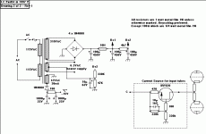
Apart from that, i wonder why the original supply (see below) uses enough filtering to bring the ripple down to a few mV? Is it because of the HF noise of the SS diodes in the rectifier? Or just oversized filtering to provide an "as good as possible" B+?
Another thing, how much voltage do I need on the negative rail for the tube CCS? I have some mains transformers lying around for the project, and there would be a 50-0-50 winding left to be used for the negative rail. But that means that after tube rectification / filtering I have about -70V available? Is this enough for a tube CCS?
Greetings
Andreas
Attachments
hm,
does the circuit see much of the design of the current source, as long as it is on the correct potential and draws the same current as the original one?
It makes sense to use the given CCS, and it is definitely easier with SS devices, but my overall design idea was to build the whole amplifier without solid state... Not for "religious" reasons , I build SS circuits as well, but I just liked the idea...
Greetings,
Andreas
does the circuit see much of the design of the current source, as long as it is on the correct potential and draws the same current as the original one?
It makes sense to use the given CCS, and it is definitely easier with SS devices, but my overall design idea was to build the whole amplifier without solid state... Not for "religious" reasons
Greetings,
Andreas
With regards to the orginal question, it depends on the PSRR of the amp. In Randy Slone's book he says that a 2V peak to peak ripple is acceptable for his SS power amps because they have relatively high PSRR.
I built a simple common cathode 12B4A line preamp. With LCRC (10H, 470u, 2.2k, 240u - not that it is ideal but I happened to have the parts) I could hear the 120hz from the speaker when closer than a metre and it was noisy. This is about 1.5mA ripple. Note that after the power amp gain of about 30 the noise can be very bad. With LCRCRC I can hear it when my ears are close to the speaker. When the parts arrive I will make it LCRCRCRC and the ripple will be 0.01mA and I reckon that is close to DC and it should get rid of all the noise.
Regards,
Bill
- Status
- This old topic is closed. If you want to reopen this topic, contact a moderator using the "Report Post" button.
- Home
- Amplifiers
- Tubes / Valves
- How much ripple on B+ is allowed?

