That means the first stage has too high output impedance because of the cathode degeneration, or the signal level is too high.
This diode trick is commonly used so should work OK given the right circumstances.
A neon is an alternative.
You are correct. I played around with the sim and if the Rp and Rc values on the first stage are "tuned" The distortion with and without the diode remains virtually the same. As McG has it they are not.
Last edited:
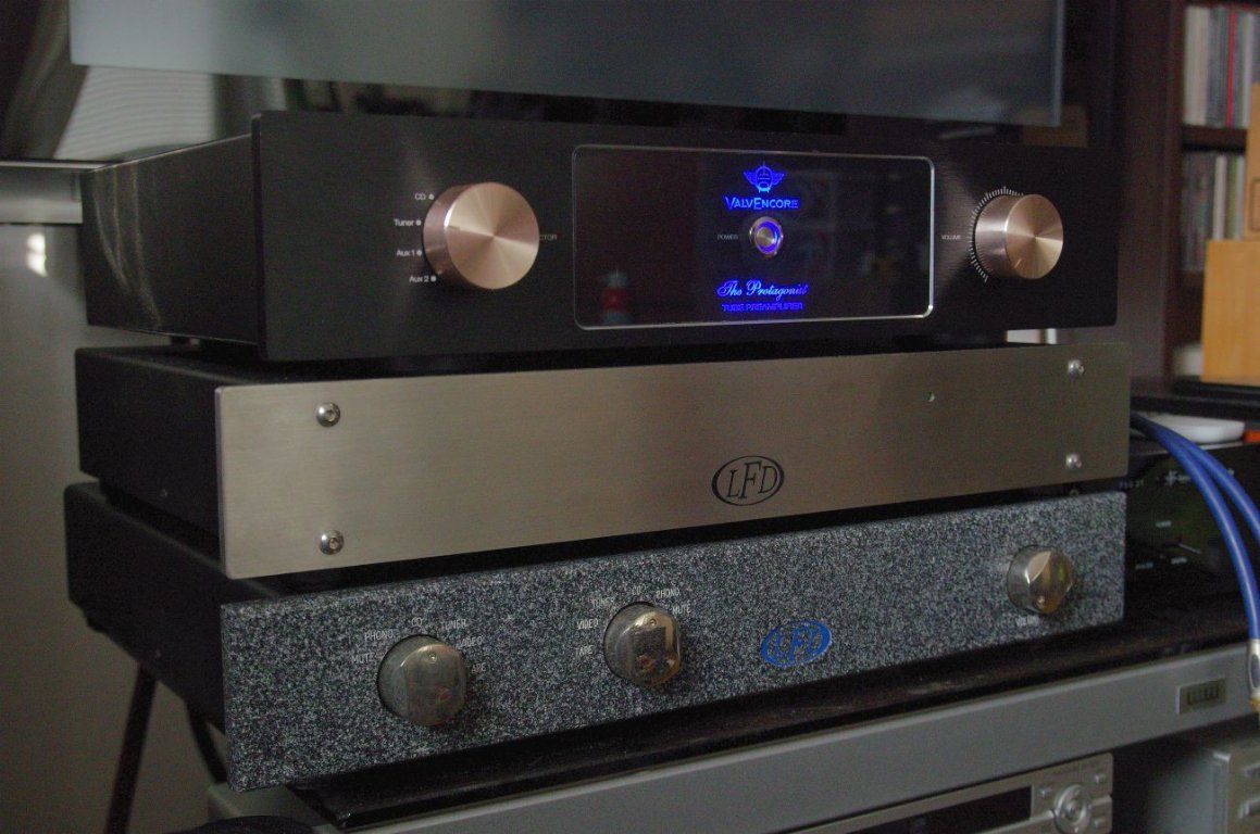
Preamp
Hi where can I find the full schematic for amp and power supply plus spec's on it
Cheers.
Konnichiwa,
Surprisingly this circuit is practically exactly that of the linestage of the full function Kondo M7, including the paralelling of unequal value cathode resistors, except for the most important part, the valve. This should be a 6072A, NOT 12AU7.
Also, Kondo builds the circuit hardwired, on copper chassis and using his own Silverfoil & Mylar capacitors plus tantalum resistors....
Sayonara
Hi where can I find the full schematic for amp and power supply plus spec's on it
Cheers.
Yes, I agree.
Is there one operating point that is optimum for a 5687? I like the one I have a lot. Seems more bias current yields better sound, just like class A SS amps, with guidlines and limits not exceeded that is. I have read Low mu tube, high current, high mu tube low current seems best.
And one more Q for you all. Paralleled tubes - the output impedance is halved? Gain doubled? I can see the smear issue, but both sides in a 5687 tube should be matched?
the operating point aspect may be easier to grasp by starting at the output and working backwards. the output stage has a lot of current gain and slightly negative voltage gain. from the large k series resistance we can infer that the designer has assumed that the load will be hi-z. the output stage will present an even higher-z to the previous one. thus the previous stage will not need to source much current--nearly none. the allows for the use of both a reasonable plate supply voltage and a large anode resistor which behaves more nearly like a current source than a lower value would thus improving linearity. the high bias point allows for a reasonable anode supply voltage despite the large anode resistor. of course if the operating point is pushed too low (ie: even higher negative bias) linearity will degrade. so what we have here is the designer finding the sweet spot where he can exploit the cathode follower and its assumed high-z load to present an extremely light load to the previous stage and that allows him to pick an operating point that is very favorable in terms of linearity while keeping the plate supply voltage within reason. paralleling lowers the characteristic internal plate resistance of each stage which furthers the designer goal of making the anode feed closer to current source behavior. IMHO it is all very clever. the more traditional approach isn't all bad, however. all this hi-z, low current stuff has its price in terms of not supporting ill-mannered loads too well and increased sensitivity to external noise sources. both because of that aspect and the low PSRR of a pure single-ended design, this circuit will be quite sensitive to weaknesses in the PSU.
Now armed with all this it is easy to see that the 6922 design a few posts back is not really an AN7 clone. It's actually a good and relatively standard-design 6922 setup (except for the diode which would be replaced with a shunt neon bulb or removed as made needless by dint of a PSU soft start). see, e.g.: http://www.augustica.com/designing-6922-cathode-follower-ezp-17
Last edited:
If so, the only way to protect the tube from arcing at startup is to delay switching on the anode supply. 40-60 seconds will do.
the neon shunt will work and is very quiet
I never claimed that my approach is really a "clone", I only stated that is inspired by Kondo M7 and Klimo Merlin. And my setup isn't accidental, it allows me to drive almost any power amp, be it tube or solid state.(...)
Now armed with all this it is easy to see that the 6922 design a few posts back is not really an AN7 clone. It's actually a good and relatively standard-design 6922 setup (...)
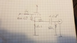
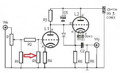
Schematics here:
P-100k black Alps
R1 - 820k
R2 - 1k
R3 - 8k2/2W
R4 - 150R
R5 - 15k/2W
R6 - 220k
C2 - 0,47uF Audyn True Copper
C5 - 47uF/250V
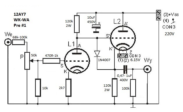
The diode function requires a commentary. This circuit suffers from the problem that on start up, the grid of second halve will immediately rise to HT potential while the cathode is still cold and tubes conducts no any current. It causes arcing between the electrodes, and rapid destruction of the valve. This problem can be easily resolved by connecting an ordinary rectifier diode (such as a 1N4007) between grid and cathode. At start up, this will keep the cathode within a few tens of volts of the grid. Once hot, the valve will bias with the cathode at a higher potential than the grid and the diode will be reverse biased, off. It will be present only as junction capacitance (few PF) between cathode and grid, wchich is negligible.
Simple mosfet regulated anode power supply:
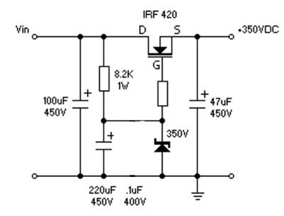
(in my preamp zener diode is 180V, not 350V)
Very very interesting.
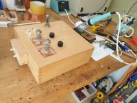
I'm currently building this setup with ecc2000 tubes.
I came across your post after googling the arcing issue I had 😉
I also discovered that this dc coupled Kfollower isn't really intended for audio but for Gitar as it seems to compress the upper wave of a sinus. I will digg into that a bit deeper.
Here are some photos of what I work on.
Attachments
@McGyver
I wanted the edit my post as I had something more to say, but that didn't work.
First, thanks for sharing your design.
Second, I use same values for Ra and Rk2, I currently have a bias of 1.6V for both triodes.
May I ask why you choose for different Ra Rk2 values?
I wanted the edit my post as I had something more to say, but that didn't work.
First, thanks for sharing your design.
Second, I use same values for Ra and Rk2, I currently have a bias of 1.6V for both triodes.
May I ask why you choose for different Ra Rk2 values?
My latest implementation:
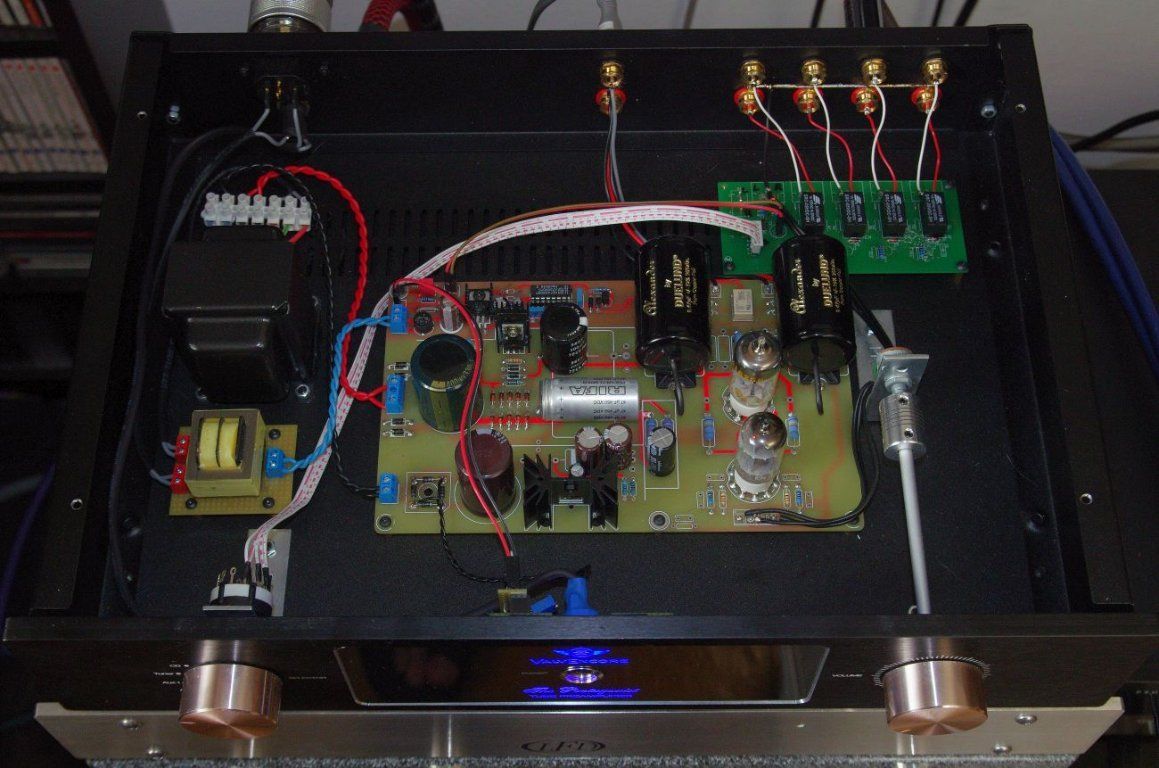
12AU7 tubes used, with 250V B+ and different resistors values of course.
Arcing protection diodes:
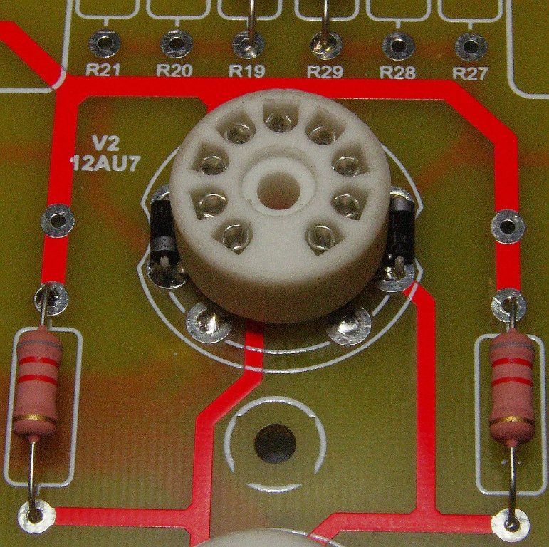
Component values for 12AY7 version:
Te handmade preamp shown above sounds slightly better than original Kondo M7 in dynamics, precision and space also.
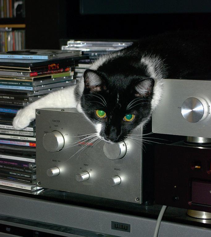
Now only the cat remained and Kondo was gone. No reason to keep it, since the handmade preamp sounds better.
12AU7 tubes used, with 250V B+ and different resistors values of course.
Arcing protection diodes:
Component values for 12AY7 version:
Te handmade preamp shown above sounds slightly better than original Kondo M7 in dynamics, precision and space also.
Now only the cat remained and Kondo was gone. No reason to keep it, since the handmade preamp sounds better.
Dear All,
I have been following this thread and would like some help converting this into a 12au7 ecc82 cathode follower line stage like the Kondo M7 if possible.
I already have a B1 voltage of 250 volt and a 6.3 volt filament voltage.
The layout of my pcb is for the ecc 81 82 and 83 tube with a similar cathode
follower a la CJ PV 10 that can be easily converted.
Any help would be greatly appreciated.
Thank you!
I have designed something like that, but I'm on vacation now. PM me next friday and I'll help you.Dear All,
I have been following this thread and would like some help converting this into a 12au7 ecc82 cathode follower line stage like the Kondo M7 if possible.
I already have a B1 voltage of 250 volt and a 6.3 volt filament voltage.
The layout of my pcb is for the ecc 81 82 and 83 tube with a similar cathode
follower a la CJ PV 10 that can be easily converted.
Any help would be greatly appreciated.
Thank you!
- Home
- Amplifiers
- Tubes / Valves
- Audio Note M7 Line Preamp??