this is my first amp build, and i am using the monoblock kits from antique electronic supply.... instead of following the kit exactly, i am mounting it on an aluminum chassis... im using a front mounted power switch, chassis mounted binding posts, and a detachable power cord...
my first question is how do i hook up the power switch and still use the fuse that is supplied... the kit comes with a switch mounted on the power cord, which i am not using
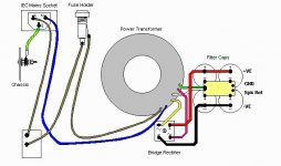
this is what i have so far

is this correct???
this is a huge learning experience for me...... next time ill try point to point
my first question is how do i hook up the power switch and still use the fuse that is supplied... the kit comes with a switch mounted on the power cord, which i am not using
this is what i have so far
is this correct???
this is a huge learning experience for me...... next time ill try point to point
EC8010 said:Fuse first, then it protects you from a fault in the switch. Even better, use an IEC socket with built-in fuse.
No ...Double pole switch first then fuse.....safety directive....
Why ? if power cord is reversed a double pole switch will avoid the possibility of shock from a damaged fuse or holder from current flowing round other part of live circuit. I now fit double pole switches with a neon inside.
Also. My mains supply is split phase 2x 115V so in practice both power pins are actually live but an electric shock will only be 115V.
richj
richwalters said:No ...Double pole switch first then fuse.....safety directive....
Why ? if power cord is reversed a double pole switch will avoid the possibility of shock from a damaged fuse or holder from current flowing round other part of live circuit. I now fit double pole switches with a neon inside.
I see the logic, but an IEC lead isn't reversible. Is the plug into the wall outlet reversible? We Brits have non-reversible wall outlets, and we like a fuse in our IEC inlet so that we are protected against any fault, including the switch (there was a thread on here recently discussing a switch that gave a member a shock).
im lost......
i will be using an IEC outlet, but it will NOT have a fuse in it.....im using the inline fuse from the kit.....
there will be 3 wires coming off the IEC into the chassis (pos, neg, ground i assume) .... the power will lead down to the power switch which has 2 wires.... where should i put the fuse???
and the ground should just goto the chassis correct??
Murphies Law....in the entertainment industry someone in a hurry or in bad light is bound to wire the cord the wrong poles, and this is just what happens.
There is another problem that can arise when the switch is in the wrong place......esp in off line switchmode equipment which uses X & Y input filter. I've seen alot of US power supplies modified for European, and the Y filter cap values unchanged would in practice pass double the current permitted.
For hard wired systems using cable entry and grommet .. the earth wire connection should be the longest within the apparatus compared to the other AC ones, that-it- is- the last wire to detach itself from equipment if some *** trips over the cable and pulls the other AC ones out. The cord grip also comes into the equation but I've mentioned enough.
All of this comes under User safety regulations in various approvals houses....naturally all information is given in good faith.
richj
jdbrocious said:im lost......
i will be using an IEC outlet, but it will NOT have a fuse in it.....im using the inline fuse from the kit.....
there will be 3 wires coming off the IEC into the chassis (pos, neg, ground i assume) .... the power will lead down to the power switch which has 2 wires.... where should i put the fuse???
and the ground should just goto the chassis correct??
I alway's wire my amps with an IEC inlet module (no fuse, I use a separate fuse holder like you).
Black wire (hot), should have the letter "L" on the back of the IEC inlet, goes to fuseholder first, then power switch.
Other side of power switch goes back to power transformer.
White wire (neutral) goes directly to the power transformer.
Green/Yellow wire (ground) goes directly to the chassis right next to the IEC inlet, keep this wire short.
Others may have other methods, but I find this is very common on a lot of shematics I've built (US based).
Glenn

Here is a good example except that the switch is breaking both the hot and neutral sides of the line.
Glenn
An externally hosted image should be here but it was not working when we last tested it.
Glenn
You have a single-pole switch. N (neutral) wire goes from IEC connector to transformer. L (line or "hot") wire goes to fuse, then switch, then transformer. If it's a chassis mount fuseholder, wire from IEC connector goes to BACK terminal, SIDE terminal goes to switch.
Diagram shows switch wired first, which is NOT the preferred connection. G (ground) terminal should be grounded to chassis with its own screw - don't share with other ground connections.
If you have a friend who's an electrician, electrical tech or engineer, ask him/her to look it over before you plug it in.
Tom Bavis said:You have a single-pole switch. N (neutral) wire goes from IEC connector to transformer. L (line or "hot") wire goes to fuse, then switch, then transformer. If it's a chassis mount fuseholder, wire from IEC connector goes to BACK terminal, SIDE terminal goes to switch.
Diagram shows switch wired first, which is NOT the preferred connection. G (ground) terminal should be grounded to chassis with its own screw - don't share with other ground connections.
If you have a friend who's an electrician, electrical tech or engineer, ask him/her to look it over before you plug it in.
Tom is correct, like I said in my text only post, the fuse should be the FIRST thing the hot lead goes to.
I didn't catch that in the picture, sorry.
Glenn
ok, now that ive got the power taken care of.....
how should i go about eliminating the volume control from the kit....
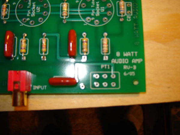
ive picked up a 470k resistor as i was told that would do the trick.... but where/how on the PCB should i have it??? there are six holes where the volume control would seat
and also.... im mounting the binding posts on the rear of the chassis... can i just solder copper wire on to the PCB to extend out to the binding posts?
thanks for all the help everyone.......this is one hell of a learning experience!!!
how should i go about eliminating the volume control from the kit....
ive picked up a 470k resistor as i was told that would do the trick.... but where/how on the PCB should i have it??? there are six holes where the volume control would seat
and also.... im mounting the binding posts on the rear of the chassis... can i just solder copper wire on to the PCB to extend out to the binding posts?
thanks for all the help everyone.......this is one hell of a learning experience!!!
another question......since im using chassis mounted tube sockets, i am using lead wire from the PCB up to the chassis..... normally the tube sockets would be right on the PCB, but this will not work with my layout.
anyway, will 16awg copper wire work fine for the lead wires??? the distance from the PCB to the sockets will not exceed 1/2" and i am planning on twisting the 9 lead wires together to eliminate noise (this was suggested to me)
anyway, will 16awg copper wire work fine for the lead wires??? the distance from the PCB to the sockets will not exceed 1/2" and i am planning on twisting the 9 lead wires together to eliminate noise (this was suggested to me)
A schematic or picture of the board would be helpful.
I'm not sure why you would need a resistor in place of the volume pot. Without the resistor it would run at full volume (I assume this is what you want), and with the resistor it would run at minimum volume (depending on how the resistor was wired in place of the potentiometer. ) This is assuming the resistor is the same value as the original potentiometer.
There should be only 3 circuit connections for the volume pot.
Again it's difficult to comment without a schematic.
I can't see much on the AES web page as the picture is very small.
Glenn


I would think 16AWG would be fine for the tube socket wires. Be sure it is rated for 300V as the 11MS8 tube has a max plate voltage of 250V (Don't know what this amp is actually using for B+). Be sure to twist the wires from pins #4 & 5 as these are for the heaters. Observe proper wire dressing for these wires for low noise (hum). Do a search on heater wire dress & hum on this site as this has been discussed many times here I'm sure.
Here is a link to the tube datasheet:
http://www.nj7p.org/Tube1.php?tube=11MS8
As for the volume pot, I see one trace on the top connected to one pad on the PCB coming from the capacitor on the left. How many traces are connected to the pads on the opposite side of the board? Again, did they give you a schematic with this kit?
It's more difficult to figure this out (not impossible) without a schematic.
A photo of the opposite side of the board would be helpful.
In the meantime, try and trace the signal path from the center of the RCA jack to the volume pot mounting area. I think one of the pads from the volume pot should eventually go to pin #2 of the 11MS8 tube. Maybe someone else is more familiar with this tube. I myself have never used one.
Glenn
- Status
- This old topic is closed. If you want to reopen this topic, contact a moderator using the "Report Post" button.
- Home
- Amplifiers
- Tubes / Valves
- first amp build... wiring questions