Hi all,
I've been working through a PP design using 6SN7 splitter (diff. pair) with 6BX7 Constant Current Sink, 6SN7 driver (diff. pair) with similar CCS and 6L6 output (Class A1), with 6CW5 CCS.
I have some questions!
*Do I need to tie the grids to any sort of reference, or does the effect of the CCS dictate the operating points?
*As the circuit is, there are only capacitors between the stages, with no grid leaks or stoppers. Is this OK, or do I need to place grid stopper resistors after each coupling cap?
*Can I put global feed back to the grid of the first valve, mixing with the input signal (it's capacitively coupled to the source) or will this have adverse effects on input resistance etc?
Thanks for advice and suggestions in advance... Bob
Grids always need to be returned to some sort of reference. A CCS will let you cheat a bit on the size of grid leaks, though.
Grid stoppers are usually a good idea.
Return back to the grid of the input stage is possible, but can have disadvantages in some applications (e.g., input impedance, noise). The summing point is a virtual ground, so the input impedance will roughly equal the series resistance beteen input and the summing point.
Thanks SY,
Can I then derive a reference for the grids by a simple deviding network between B+ and gnd, on which the signal will be superimposed, or is there a better method without resorting to -ve supply rails?
Where can I inject some feedback on a differential pair CCS stage?
I assume that putting feedback to the cathodes (CCS anode) will unbalance the stage, defeating the object of the CCS, is this correct?
Is there any other method of reducing gain and distortion without NFB?
Perhaps local feedback somehow?
Thanks for the help... Bob
Ok, here's the schematic I drew. Sorry about the qulity, but I don't have a scanner or any drawing packeges on this mac!
Please tell me if I've made any really bad mistakes, or and mods that would improve performance.
You said I need to tie the grids to a reference, so where would that be?
Is it worth having the CCS in the output stage? I thought it would keep a perfect balance and eliminate transformer DC flux?
Where might feedback be applied?
Thanks again...Bob
Attachments
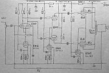
This is going to take some work. Let me hit two things first: the output stage CCS and the grid reference for the 6SN7s and the outputs.
Output stage CCS is something of a fashion at the moment. It's OK if you want to stay in class A (big sacrifice in power), but you have to think through carefully what happens with overload. And in a power amp, you WILL overload the output stage from time to time. Nonetheless, if you want the output stage to run as a CC diff amp, the current sink has to handle a lot of power, and the EL86 you have won't. You'll need a power tube roughly as hefty as your output tubes.
The first 6SN7 would have a grid reference to ground via the feedback resistor and the output transformer secondary, except you don't have the secondary grounded. You've also returned the feedback resistor to the input grid, which is curious. And it will be a big problem. Since you're running the first stage as a diff amp, why not take the input to one grid, then the feedback to the other?
The second 6SN7 has no grid reference whatever. With some juggling, you should be able to direct couple the first and second stages which takes care of that problem. If you go that route, you'll have to run the second 6SN7's heaters separately, biased up sufficiently so as not to exceed the maximum heater-cathode voltage limit. If you have a copy of Morgan Jones's "Valve Amplifiers" (you DO have a copy, don't you?), take a look at how he does this in the Crystal Palace driver stage.
You're also going to run into trouble trying to get the second stage to swing enough voltage cleanly to drive the outputs because of the undersized plate resistors. That's the least of your problems- the biggest is that the output stage grids are also not referenced to anything. If you're going to run an output stage CCS, you want each grid referenced to ground through a moderately large grid-leak (sat 470K or so).
Ok, I made some changes.
I've lost the output CCS altogether in favour of an adjustable bias/ balance configuration, tied the grids down, altered the operating point of the driver stage CCS to use larger anode loads, grounded the output secondary, moved the feedback point as suggested and finally added some grid stoppers!
How's it looking now?
Will it be ok to run 6L6's at 375V in triode mode? The data sheet suggests 250V so I'll probably need more cathode bias resistance (another 100R in series).
I had planned the output CCS to loose 125v and was aware I would need to dissipate more power than the EL86 could manage, but hadn't yet got to it.
Yes, I have Morgan Jones's Valve Amplifiers, but it's the second edition with no mention of 'Crystal palace', however, there is a circuit showing a splitter using LM334Z CCS and EF184 CCS for the driver stage. There is no global feedback used in the circuit.
I built a variation of the 'bevois valley' amp a couple of years back and it's performed flawlessly ever since. Very nice.
Thanks a lot for taking the time to correct my numerous mistakes!... Bob
Attachments
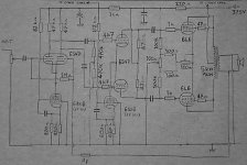
I'll try to give you a more comprehensive answer later when I have some more time, but quickly:
1. Get the Third Edition of Valve Amplifiers. Trust me on that one.
2. You're going to have to think about how you want to get sufficient voltage across the CCSs, along with getting their elements biased properly.
3. You've got essentially 100% feedback. Is that what you want?
More later. Gotta go.
1. Get the Third Edition of Valve Amplifiers. Trust me on that one.
2. You're going to have to think about how you want to get sufficient voltage across the CCSs, along with getting their elements biased properly.
3. You've got essentially 100% feedback. Is that what you want?
More later. Gotta go.
Hi Bobhayes,
Not to steal SY's thunder (he is doing admirably) but perhaps a few points from me while he is resting:
1. Do not apologise for your drawings; they are quite neat and legible. You should see some of the "back-of-cigarette-box" stuff that otherwise neat sites post - yuch! Then such a man want me to respect his design! But enough.
2.
Sorry! I have pushed the wrong key and things went off before I had finished. To continue:
2. I agree with SY that the use of CCSs is sometimes overrated. They certainly have their use, but in some applications the advantage in audio is minimal at quite some extra expense and complexity. For the driver 6SN7 I see no advantage over a 390 - 470 ohm cathode resistor. CCS will only guarantee equal current in both triodes, not equal amplification factor if the units are not equal; for the latter you will still have to balance with a pot between the 47K loads if you want it precise. Also with a valve the about 5V bias needed is too low for proper pentode CCS operation. I have never used it myself, but it seems that even for the quite low anode capability of a 6AU6A at least about 25V will be needed on the pentode anode. (Only transistors will work at 5V).
3. With the input stage you can of course have about 60 - 80V on the cathodes - but then not with the second grid tied to common (through NFB). You will need a separate cathode resistor up top with 2 grid returns to set up proper conditions. In general I would suggest setting up with about 100V - 120V across the tubes and another about 120 - 150V across the anode load resistors to get into the linear region. As SY suggested, I think that unity feedback with this circuit will be too much; you will need further caps and a resistor divider for this. (Here I apologise for not posting a circuit right now. I have the same problem as you.)
3. You ask about triodes: The 6L6GC can work with up to 500V of h.t. (the actual voltage will still be some 40V less because of cathode bias). You will need to keep within the 35W plate dissipation rating for triode mode. But I will not ignore the use of ultra-linear or distributed load mode (screens tapped onto output transformer). To me there is a nett advantage; you have almost triode operation but at tetrode output capability. Data shows that up to the 15W max that the pp triodes can give, UL will give lower distortion.
Then you can peacefully use 470K grid resistors here instead of 100K; it will ease ac loading on the driver 6SN7.
4.
Ach no! There is something the matter here. My sincere apology (also to moderators) for sending stuff before I have finished - cannot imagine why. Just one more point then (it should all have been the same post).
4. I would advise using larger series resistors in the power line than 220 ohm and 1K (if I recall correctly). These together with the bypass capacitors (values unmentioned) are supposed to decouple, and unless you want to use enormous C-values, rather try about 10K - 22K or even higher. The voltage drop should not be too much. Then 16uF - 32uF should be enough.
Quite a lot from me but hoping it will be of assistance to you (bowing out before the PC surprises me again).
Thanks Johan for taking an interest in my terrible mess.
I've learned that I am not at all clever enough to design a valve amplifier!
I have read Morgan Jones's book several times from cover to cover, and frequent it as a reference, but cannot absorb the information contained therein.
I am hereby declaring defeat, and am going to build a williamson from someone else's schematic instead.
Thanks again for all the help... Bob
There's a big difference on complexity between a Williamson and what you were originally proposing. If you've decided that your original idea was too complex for you, why not sneak up on it bit by bit? Build something with the potential to be developed into something more complex. That way, you'll have an amplifier that works at all stages of the game and it will be a learning tool.
Thanks for the encourageing words EC8010.
Your suggestion sounds good. Do you mean building a simplified amplifier using similar tubes and stages, in a more basic form, and adding CCS's etc when I understand how to execute them properly? Now that's not such a bad idea.
I have seen a few nice looking schemetics around the web but none of them looks quite 'right' for me. I wanted to use 6L6's, but can't find any schematics I like which use them.
I reckon it wouldn't take a lot to modify some of the EL34 or KT66 circuits for 6L6.
That's something I might look at.
Thanks again... Bob
You're right, it shouldn't be difficult to modify an EL34 circuit to use 6L6.
Yes, I'm suggesting that you do the metalwork to take whatever valves you're thinking of finally using, putting all the heater wiring in place, but building a simple audio circuit first just to get it working. Then add a CCS and see how you go. The reason I suggest doing all the holes and heater wiring first is that it's hard to do them later...
Yes, I'm suggesting that you do the metalwork to take whatever valves you're thinking of finally using, putting all the heater wiring in place, but building a simple audio circuit first just to get it working. Then add a CCS and see how you go. The reason I suggest doing all the holes and heater wiring first is that it's hard to do them later...
No, No, No Bob, you do not declare defeat. You carry on; you have already learnt and that is progress! (How do you think the rest of us got there?) I still make ghastly mistakes, but MERCIFULLY these days it is on Spice; when I route 5A through a tiny transistor, I can simply press a key after making sure nobody noticed that I was a fool.
I myself grew fond of the old Leak TL12 circuit, but not to play off against other circuits with merit. My main contribution here is to perhaps point out that the main difference between EL34 and 6L6 is gain and bias; the 6L6 needs a higher input voltage and bias resistor (one cannot directly replace). The 6L6 and KT66 is so similar that Russians often use the same innards and even call some tubes a 6L6WXT/KT66 (lower heater current for 6L6).
Enjoy!
Bob, you've gotten some excellent strategic suggestions here. I think the idea of starting with something simpler, but punching enough holes to end up at your dream amp, is an excellent one.
I've seen some very nice stuff using your ultimately-desired topology posted here. If memory serves, ray moth and gingertube were using cascaded diff amps...? Might be worth spending a few minutes searching for their schematics and figuring out why they did what they did.
I've seen some very nice stuff using your ultimately-desired topology posted here. If memory serves, ray moth and gingertube were using cascaded diff amps...? Might be worth spending a few minutes searching for their schematics and figuring out why they did what they did.
Thanks for the encouragement everyone. You've kick started me again!
I have studied the schematic posted by eric (above) before, but was looking for something like SY is describing. Unfortunately, I can't seem to find any trace of the schematics by searching.
I really like the idea of punching a chassis for more sockets than are currently required, as my current 2A3 se amp could have been converted to PP if I had thought ahead! Still, I like it as it is and would rather try something else.
Does anyone know of a schematic to study which uses 6SL7/6SN7 input, 6SN7 driver and 6L6/KT88/EL34/5881 or whatever output (It's the input and driver stages I'm most interested in studying).
I've downloaded lots from various sites, and am particularly interested in finding more with directly coupled stages to study their operation more closely in conjunction with the curves and data sheets.
Can anyone give their opinion of this topology. I don't know if the input section looks quite right. Can it really be that simple?
http://audiotropic.netfirms.com/Projects/ampEL34.html
Thanks again for the motivation... Bob
- Status
- This old topic is closed. If you want to reopen this topic, contact a moderator using the "Report Post" button.
- Home
- Amplifiers
- Tubes / Valves
- CCS, feedback and grid leak questions.