Yes, I had a good look at that schematic, and I do like it, but I'm not ready to get into negative supply rails yet.
I reckon I'll have a go with the cascode input mullard type circuit, and maybe modify it for a CCS on the diff/driver stage at a later date.
I'll use 6L6 output tubes and adjustable self bias on the 6L6's instead of the fixed bias shown. This can be modified later on too. Many people here are saying fixed bias is the only way to go really, I guess because no power is lost in the bias arrangement, and there are no bypass caps to screw up the frequency and phase behavior of the output. Is this correct?
How does fixed bias improve the output stage, and what are the technical reasons for the improvement?
And finally, do you think I should punch a chassis for B9A and octal sockets so I can play with different tubes?
Cheers... Bob
Although PP cancels even harmonic distortion at the output transformer, each individual valve distorts and produces distortion proportional to level. 2nd harmonic distortion implies a change in the DC component of the signal, and the cathode bypass capacitor integrates that change. In other words, the bias on each valve gently meanders around depending on signal level. Grid bias doesn't do that.
Yeah. . . . The old problem of having to point out a difficulty without appearing to criticise the author. I do enjoy Poinz's contributions tremendously, but have a problem with his description attached to that diagram (was it post #20?). And as Bob is looking for information and trying to learn:
The circuit is in fact very close to the original Leak TL12 that I have used a lot. I found no problem with a pentode input stage and argued my case before, but will leave it at that - no burning feelings. What did puzzle me was the exchange without more ado (if I read correctly) of a 6SL7 and 6SN7 for the input tube. The two are nowhere near the same! The SL is a high-slope triode with a mu of 70; the SN a medium-slope triode with mu of 20 or less. To illustrate: For a plate current of about 2.3 mA at 250V the SL will require a bias of 2V; the SN all of 11V! Apart from the 3x or more increase in amplification (and thus feedback factor), the driver grid voltage of 113V (which is about right for this operation) is going to vary so widely with such an exchange without bias resistor adjustment that a comparison will be meaningless. (This is not the first time that I have encountered such comparisons without the conditions being checked.) So beware here, Bob.
I have also mentioned elsewhere that a high-mu triode with an input volume control can give variable performance dependant on its setting because of Miller-effect; it has been called "the sonic signature of the volume control". This is especially risky with tubes with mu's of 40 or more, with high value volume controls. The use of a current triode (not cascode) for the input load is OK since there is a triode available, but will not affect the performance noticeably because the signal amplitude is so small that a resistor would do equally well - it is with larger amplitudes that a resistor starts introducing 2nd harmonic distortion.
EC8010 has described the difference between cathode and fixed bias; especially in class AB circuits you will find that the output tube current increases as output goes up, which leads to a larger bias across a cathode resistor, decreasing the current again and limiting the output. On the other hand this is self-regulating; with fixed bias one needs to assure that things do not "run away" - that process is a little longer to describe.
But there is an intermediate way: For music output, peaks are not maintained for very long compared to the general level duration. Thus you can have almost fixed bias (or at least much of the effect) by shunting your cathode resistors with whacking big electrolytic capacitors to maintain short-term constancy - in these days of small efficient components this is a prctical alternative.
This is becoming long, so I will stop for now. My main problem was with the injudicious exchange of different valves and resultant misleading results.
Thanks for the info.
Yes, I was very aware that you can't just plug in a 6SN7 where the 6SL7 is, and understand the theory of loadlines, current and bias in triode stages. Not a problem. (pentodes are still beyond me, but I'm getting there)
So the upper valve of the input stage is actually a constant current source as it's bias is fixed by it's cathode resistor (grid connected beneath)?
I know that the voltage drop over the cathode bias resistor is current dependant (ohms law), and that bypass caps 'regulate' the effect by creating a sort of virtual ground (is that an appropriate description?).
I suppose you could compare the electrical difference between fixed and self bias to the acoustic difference between horn speakers and sealed boxes, where horns remain linear at high level, closed boxes suffer from power compression, and the volume of the box is comparable to the size of the bypass capacitor, is that a fair comparison?
Morgan Jones states that the problem with the original mullard bias, is the small value of bypass cap used, due to availability. 50uF just ain't enough, but to be aware of capacitor inductance with larger values.
I can now see the advantages of fixed bias, but I'm keeping it simple for now.
Thanks... Bob
SY said:That's a variant of the old Mullard circuit, but substituting a cascode for the input pentode.
Totally wrong, dude- the opportunity for the cascode was missed and input stage is just a common cathode triode loaded by a mediocre current source. What WERE you looking at? You're right about the phase splitter, at least.
You oughta listen to that Johan guy.
")
Johan, a big bypass cap in the cathode circuit works great as long as you don't overload the amp. Unfortunately, it also slows recovery from overload. Tradeoffs, tradeoffs...
Two work-arounds that are simple would be:
put a zener across the bypass cap to limit how high it can charge
or
if you have a tube that only requires a modest bias like EL84, use a set of parallel LED strings.
Two work-arounds that are simple would be:
put a zener across the bypass cap to limit how high it can charge
or
if you have a tube that only requires a modest bias like EL84, use a set of parallel LED strings.
Now we're cooking on gas!
Zener and big cap... elegant and simple.
Can I use adjustable balance and bias controls (aka williamson) for the output bias and use a bypass cap and zener, or does the balance control rely on AC conditions?
Can you direct me to a schematic using a cascode input stage as I wouldn't want to miss an opportunity.
Thanks yet again... Bob
Ok,
Can anyone please tell me if I have bade any horrible mistakes with this one?
The zeners are marked 15v, but should actually be 18v, and the cap from 6SN7 grid leaks to ground should be 250v rated (not 100v as shown).
I havn't labelled the feedback resistor, as I was going to use trial and error for max output for CD input (maybe 47k as a start?)
Thanks... Bob
Attachments
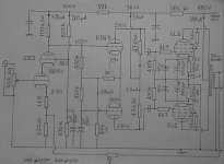
I don't see any serious problems, but there are more components than necessary in two areas.
The first one is rather interesting and shows the evolution of the Schmitt phase splitter. You have DC coupled the output of your input cascode to the next stage, which is great. You then looked at the other valve in the phase splitter and wondered how to bias it, so you added the usual cathode bias resistor and a pair of grid-leaks. Because the whole thing was at an elevated potential, you added a 47k resistor to ground from the bottom of the cathode bias resistor.
It will work, but you don't need such complexity. The valve that you have DC coupled to the input stage has a DC path to ground from its grid (the anode load of the previous stage), and its cathode potential will be almost equal to its grid potential. Since we can see a large resistance to ground (1k + 47k), that will define the current through this valve. We can remove the connection between the two grid-leaks and the junction of the 1k and 47k. We now see that we have a pair of 1M resistors in series, so we can combine them into a single 2M (or 2M2) resistor, and 47k plus 1k is near enough 47k, so let's throw the 1k away. Will it work? Yes, the second valve has the same DC path to ground as the first, so any changes in the DC potential of the cascode will be tracked by both valves and rejected by differential action. That's great. At audio frequencies, the 1uF capacitor is a short circuit to ground, so the stage amplifies audio frequencies. You now have a Schmitt phase-splitter. Depending on the LF stability once global feedback has been applied to the amplifier, you might not need quite such a large capacitor as 1uF.
And talking of global feedback, you have applied it to the cathode of the input stage in the traditional way with a 100R resistor down to ground but have omitted the capacitor across the upper resistor to the cathode. If you applied the feedback directly to the cathode, you can drop the 100R resistor. Calculating the value of the feedback resistor becomes much harder, so you might prefer to just go for a suck it and see approach of putting a variable resistor in and adjusting it on the bench for the required gain.
Go ahead and build!
Thanks for checking it out. The changes you suggested have been made (although the values you mentioned were not as labelled, but that was probably the crummy picture I posted).
Great... I'll start punching a chassis, and winding some c core trannies up then! Maybe add that CCS to the driver/splitter later on, so I'll punch a hole for an extra B9A socket.
BTW EC8010, did you get my message WRT fostex horn in full range?
Thanks again for all the help with this thread, now it's soldering time at last!
Bob.
Just a little bit from me. EC8010 outlined the Schmitt design admirably. As I calculate the voltages shown should be reached. Only one thing here, the "bottom" capacitor from the (new) 2.2M to common can be much smaller (as EC8010 suggested). In fact, 10nF would already get your loop response as low as about 15Hz. You do not give the driver coupling capacitors; I would make these quite large, like 220nF or so. The point being that should you run into any low frequency instability with feedback (motorboating), you get rid of that by shifting the former mentioned pole higher (making that 2.2M series capacitor smaller). That way you avoid having large amplitudes on the drivers. Not knowing the inductance of the output transformer one can make no suggestions at this stage.
The zeners are OK, but........ The cathode voltage for 6L6s under 450V is rather around 37V instead of 16V! (That should give 65 mA anode current or about 27W dissipation. OK, a 6L6GC is allowed 34W in triode mode, but I do not trust many of the new 6L6s; rather stop a bit lower.) If you use zeners as the main cathode "resistors" you also no longer need the resistors or even separate zeners for 2 tubes - you should now balance for anode current in a different way. But the dissipation goes high; 5W for a single zener source.
This is obtainable, but here one should note the zener's temperature co-efficient. (At 35V they are more avalanche than zener.) It is thus advisable to make this up from a chain of lower values. Round about 6V will give a zero temperature co-efficient. May I suggest 3 x 5.6V zeners plus 3 x 6.8V zeners, which will bring you close to the desired value. You can now use 1W zeners or for safety perhaps the next value, which over here is only 5W, but they only cost (here) about 50c (USA) each. You could retain a bypass capacitor.
As SY suggested this is a handy source of fixed bias, but zeners are noisy. I have used this once some years ago, and as I can recall I had no addition of noise at this signal level. But perhaps others with more recent experience here can enlighten us.
Johan,
I PM'd you regarding the book you mentioned, thanks.
I've changed the ground reference cap under the driver grids as you recommended, and I've re biased the outputs using 2x390 ohms. According to the 6L6G curves for triode, with 450v and 5k output (2k5 loadline) this should give me around 23v on the Cathodes, and around 60mA through each tube.
I'll play with the bias once I get a working circuit together, maybe starting with 470 ohms or something and looking at voltages.
It never occurred to me to use zeners alone for bias, but it makes sense.
Maybe I'll play with this idea too later. There's plenty to experiment with once I get the amp up and running, but it's time for making transformers now!
Cheers... Bob
- Status
- This old topic is closed. If you want to reopen this topic, contact a moderator using the "Report Post" button.
- Home
- Amplifiers
- Tubes / Valves
- CCS, feedback and grid leak questions.