If the autoformer is in the cathode output of a power tube then this would work very well as the speaker output could reference circuit ground. In a conventional plate load circuit you would have system B+ on the speaker wire and that would be hazardous. I guess you could go to a lot of trouble and ground the positive terminal of the B+ supply but then the ground sleeve of the amplifier's RCA input jack would be at several hundred volts minus to ground. 
Of course you could parafeed into the autoxfmer from the o/p tube anode with a coupling capacitor and have the loudspeaker lead ground referenced, but now you need a plate choke for the DC supply to the output tube anode.
Rob
Of course you could parafeed into the autoxfmer from the o/p tube anode with a coupling capacitor and have the loudspeaker lead ground referenced, but now you need a plate choke for the DC supply to the output tube anode.
Rob
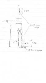
Fuling said:I´ve prototyped a PL504 SE amp with DIY OPT´s where about 25% of the primary winding is between cathode and ground, and a part of those 25%´s are wound with thicker wire and acts as secondary winding.
how did you keep the DC out of the speaker?
I did a PP amp this way which took care of the DC, but i have always feared even with a really thick secondary i would still get some DC on the speaker if it tried this with SE. Maybe a ma or 2 dc could be a good thing
dave
I suspect the benefit diminishes greatly once the transformation ratio starts to approach that required for a typical plate loaded application, however for cathode followers this could work nicely with the fairly low ratios usually required.
You could for example use a current source to bias something like a 6C33 and capacitively couple to an autoformer having a winding ratio of something like 4:1 so that it presents about a 1K load to the cathode with an 8 ohm speaker. The reduction in windings required should result in tighter coupling and lower leakage inductance than with a conventional transformer - I don't think this relationship holds well at higher ratios and I can't see the point frankly of doing anything much higher than the cited 4:1 - leakage inductances, stray capacitances and winding interleaving requirements would reduce the benefit considerably.
Just my opinion. And hmm makes me think I might want to try the above...
Kevin
kevinkr said:I suspect the benefit diminishes greatly once the transformation ratio starts to approach that required for a typical plate loaded application, however for cathode followers this could work nicely with the fairly low ratios usually required.
You could for example use a current source to bias something like a 6C33 and capacitively couple to an autoformer having a winding ratio of something like 4:1 so that it presents about a 1K load to the cathode with an 8 ohm speaker. The reduction in windings required should result in tighter coupling and lower leakage inductance than with a conventional transformer - I don't think this relationship holds well at higher ratios and I can't see the point frankly of doing anything much higher than the cited 4:1 - leakage inductances, stray capacitances and winding interleaving requirements would reduce the benefit considerably.
Just my opinion. And hmm makes me think I might want to try the above...
Kevin
Kevin,
My post was more theoretical in nature and in the case of high tranformation ratio as usually required in plate load I must agree with you. You correctly address the nuances of practical output tranformer design reality.
There are a few low Mu triodes, especially when uses in parallell that can be practical exceptions. I'm thinking 6C33, 6AS7/6080, and that expensive other one, the 6528.
Rob
Ray, one of the DC Bottleheads built a 829 amp, using a 70v line transformer wired as an autoformer. Parafeed, but without plate chokes, (he uses light bulbs).
Ray probably watches this forum, so I don’t want to steal his thunder.
So lets just say his amp sounds great…John
Ray probably watches this forum, so I don’t want to steal his thunder.
So lets just say his amp sounds great…John
Here´s how I did it:
As you can see the part that the speaker is connected to is made with considerably thicker wire, so the DC voltage across it is very small.
I don´t remember exactly, but the DCR is way below 1 ohm and the curret is around 100mA, so do the math.
This was just a prototype I made for fun and to practise my transformer winding skills, but it turned out quite good.
The bass response was way better than you´d expect from a ~3W SET with small homemade OPT´s.
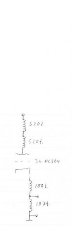
Inspired by this I´ve ordered parts to build a bigger version with 3 x PL504 per channel, each running slightly hotter than in my prototype. I expect to get 10-12W out of that beast, enough to feed my bass cabinets.
Not looking forward to wind the OPT´s though, it´s a mess...
BTW: If we connect the screen grid to a fixed voltage (WRT ground) instead of to the plate we get 25% UL operation "for free"
As you can see the part that the speaker is connected to is made with considerably thicker wire, so the DC voltage across it is very small.
I don´t remember exactly, but the DCR is way below 1 ohm and the curret is around 100mA, so do the math.
This was just a prototype I made for fun and to practise my transformer winding skills, but it turned out quite good.
The bass response was way better than you´d expect from a ~3W SET with small homemade OPT´s.
Inspired by this I´ve ordered parts to build a bigger version with 3 x PL504 per channel, each running slightly hotter than in my prototype. I expect to get 10-12W out of that beast, enough to feed my bass cabinets.
Not looking forward to wind the OPT´s though, it´s a mess...
BTW: If we connect the screen grid to a fixed voltage (WRT ground) instead of to the plate we get 25% UL operation "for free"
Attachments
2wo said:Ray, one of the DC Bottleheads built a 829 amp, using a 70v line transformer wired as an autoformer. Parafeed, but without plate chokes, (he uses light bulbs).
Ray probably watches this forum, so I don’t want to steal his thunder.
So lets just say his amp sounds great…John
Hmmm, lemme see. Red light bulbs will give a boost in the bottom end, green light bulb will enhance the midrange and blue light bulb will give more air.
Seriously, the use of a light bulb instead of a plain old resistor will add quite a different plate load depending on the average power since the resistance of a incandescent lamp varies with the current through it. A resistor does not. In the lamp, the lower the current, colder filament, lower R. High current, more heat, higher R. Add to this a thermal delay rom the mass of the lamp filament, the change in R will not be instantaneous. That HAS to have some effect on the reproduction of transients in music. It would be interesting to do a dynamic analysis of this.
Rob
Fuling said:As you can see the part that the speaker is connected to is made with considerably thicker wire, so the DC voltage across it is very small.
I don´t remember exactly, but the DCR is way below 1 ohm and the curret is around 100mA, so do the math.
i guess the question becomes how much DC through a speaker is too much? assuming an 8 ohm speaker has a DCR of what say 6 ohms and your secondary DCR is say .25 ohms (not sure exactly what well under an ohm means) this means 4ma of current will flow through your speaker. i'm not sure if this is good, bad or a non issue, but i do know it will offset the cone within the magnet structure in one direction or another.
an interesting experiment would be to listen then invert the phase of the signal and reverse the speaker leads to see if a ma or two + or - made a sonic difference.
I wouldn't be surprised if the two connections sounded different and i also wouldn't be surprised if one connection sounded better than a situation with no DC on the speaker.
dave
Most solid state amplifiers have a small amount of dc offset on their outputs, typically 100mV or less is considered acceptable as industry practice.
I have heard one of the light bulb parafeed amplifiers and it actually sounded pretty good. The output stage is operating class a and at higher frequencies at least the time constants of all of the series connected filaments seemed to be long enough to avoid noticeable compression. The one I heard had 3 or 4 240V 100W bulbs in series as I recall.
In class A amplifiers the average power is constant regardless of the power actually be delivered to the load - I am not sure at what point the hot resistance of the filament will start to vary as a function of the period of the signal superimposed across the bulb resistance. I suspect that it would probably be in the region of 30Hz or so based on observation of bulb behavior on 25Hz power. (Flickers!)
Kevin
edited typo
rcavictim said:Add to this a thermal delay rom the mass of the lamp filament, the change in R will not be instantaneous. That HAS to have some effect on the reproduction of transients in music. It would be interesting to do a dynamic analysis of this.
How long's the time constant? The thermal mass of the filament acts as a low-pass filter for the changes in plate resistance. If it's long enough (low enough) then the signal related changes in rp will be filtered out. Really, they'll never show up in the first place.
I don't think a light bulb has a time constant long enough
but maybe there something else....-- Dave
Tungsten filament bulbs have relatively long time constants, I measured some fairly high wattage bulbs ages ago and figured out using a pyrometer that some bulbs had thermal time constants of > 25mS - 30mS as I recall.. (I don't have it written down anywhere so I can't vouch for this.)
Kevin
Kevin
Fuling said:
DCR of the part that connects to the speaker is around 0,4 ohms, so I´expect about 120mA offset at 300mA plate current.
not sure i follow. if the secondary is 0.4 ohms and the DCR of the speaker is say 6 ohms (typical for a 8r speaker) then i get 20ma of current through the driver.
do you notice if the speaker cones change position (overhung/underhung) when the amp is connected?
dave
Hmm, for some reasons 20mA sounds much worse than 120mV
I haven´t tried the transformers in a circuit yet, so I can´t tell.
If it turns out to be a problem I could always just disconnect the secondary from the primary and loose some of the cathode feedback (and turns ratio)
I haven´t tried the transformers in a circuit yet, so I can´t tell.
If it turns out to be a problem I could always just disconnect the secondary from the primary and loose some of the cathode feedback (and turns ratio)
Circlotron wrote this in an old thread about choke coupled transistor amps:
I measured it again and it's 300mV. So the choke has about 1 watt dissipation at 3.5 amps. A voice coil with 5 ohms dc resistance would dissipate 18 milliwatts With my 10 inch test loudspeaker the cone offsets about 1/2 mm. Not worth losing sleep over, hey?
- Status
- This old topic is closed. If you want to reopen this topic, contact a moderator using the "Report Post" button.
- Home
- Amplifiers
- Tubes / Valves
- Autoformer output stage