Folks:
Please advise the newbie: I am considering building a tube preamp with an outboard power supply, but am questionning the wisdom of the idea. I have a nice 2-box chassis to work with, but am concerned about the demands placed on the umbilical running between the two enclosures. At very least, the umbilical will need to carry the high voltage lines for each channel and the 6.3v filament lines (there will be one for each channel) will each need to carry about 2 amps.
I'm imaging an awfully heavy gauge wire will be needed, and the umbilical will end up pretty bulky.
How dumb an idea is this?
Thanks,
Scott
Consider instead a multi-pin Amphenol style or equiv as shown on Mouser's site:
http://www.mouser.com/amphenolind/
I personally wouldn't use a sub mini-D for the high voltages and currents (heaters) of tube equipment.
Edit: Seconds too late!
http://www.mouser.com/amphenolind/
I personally wouldn't use a sub mini-D for the high voltages and currents (heaters) of tube equipment.
Edit: Seconds too late!
You should make sure that the connectors that you are thinking about using can take the voltage and the current that you are going to apply to it. I am not sure that the computer connectors were ever intended to handle this much electricity, although I did see some rated for 5 amps and 1000 volts in the DigiKey catalog. If I were doing this I would use a larger connector. In my 845SE amp I used "Cinch Jones" connectors. They have lived for two years with 1100 volts on the HV pins, and 3.25 amps flowing through the filament pins. These connectors were in the DigiKey catalog, but now the catalog says that they are only available online.
I use "test probe wire" for the HV leads, and 18 guage hookup wire for the low current filaments. I use 16 guage for the 3.25 amp filaments. You can't solder this to D connectors.
I use "test probe wire" for the HV leads, and 18 guage hookup wire for the low current filaments. I use 16 guage for the 3.25 amp filaments. You can't solder this to D connectors.
RDF:
The Amphenol connectors do look nice, but it looks like a set of four (2 box mounted units and 2 for the umbilical) will run between $65 and $70, depending on the number of pins (probably 10). Is there a cheaper option, or is this "penny wise / pound foolish" thinking?
Regards,
Scott
The Amphenol connectors do look nice, but it looks like a set of four (2 box mounted units and 2 for the umbilical) will run between $65 and $70, depending on the number of pins (probably 10). Is there a cheaper option, or is this "penny wise / pound foolish" thinking?
Regards,
Scott
Yes, there's an option that only costs half as much and is more reliable. Don't have a connector at the pre-amplifier end. Make the cable captive. You know where you're going to put the two boxes, and you know how much cable you need. Use a female connector on the power supply chassis and a male connector on the lead from the pre-amplifier.
SRMcGee said:RDF:
The Amphenol connectors do look nice, but it looks like a set of four (2 box mounted units and 2 for the umbilical) will run between $65 and $70, depending on the number of pins (probably 10). Is there a cheaper option, or is this "penny wise / pound foolish" thinking?
Regards,
Scott
You could look at Molex connectors. Not as nice or as nice looking as the Amphenols but you could do it for about $10US.
You might also consider not putting a connector on the PS. Just run the wires directly out of the chassis (through a bushing or grommet) and have a female connector on the end of the umbilical and a male chassis mount on the amp chassis.
Cinch-Jones connectors would work fine. Be sure to have the female end on the power supply. If it were my design, I'd have a male connector and umbilical comming out of the preamp, and the power supply would have the female socket on it.
I would also have one last filter stage in the preamp itslef, or at least the fiter capacitor for the first node of the power supply in the preamp (which would power the output stage).
Be sure that there is a diode in series with the +B input on the preamp chassis, since otherwise there would still be some voltage on the connector if the preamp and power supply were disconnected while running. Also be sure to add bleader resistors in Both chassis.
I would isolate the filament leads from ground in the preamp chassis, you can connect teh CT of the filament winding to ground or do whatever you like doing with your filaments in the power supply chassis. I recommend regulated filaments.
You could use smaller versions of the Varelco /Edac connectors shown here:
http://www.dhaen.org.uk/vdocs/onryoku2.htm (10th pic down)
They are much cheaper than the Amphenols you looked at. You need to order all parts separately though....
http://www.dhaen.org.uk/vdocs/onryoku2.htm (10th pic down)
They are much cheaper than the Amphenols you looked at. You need to order all parts separately though....
I agree with Dr. Photon, especially considering the fact that this is the way my 845SE is done. There is a female Cinch Jones connector on the power supply cabinet, and a male connector on the umbilical which is permanently attached to the power amp cabinet. There are electrolytic capacitors in the power supply chassis (with their own bleeder resistor) and a 2500 volt oil cap in the amplifier chassis (with its own bleeder resistor). I don't have the series diode since they are hard to find at the 2000 volt level, but it is a good idea.
I have all of the filaments grounded in the amp chassis, instead of the preamp chassis. The point here is there must be only ONE point where all of the different grounds Join together. I prefer the "star" point to be in the amp chassis, near the input connectors. This requires seperate floating power supplies for each different voltage source. In my case there are 7 different power supplies that each have seperate positive and negative leads in the cable. All of the common leads are joined at the "star" point which is on the driver PC board. This point could probably be in the power supply chassis with good results, but I haven't tried this.
I have all of the filaments grounded in the amp chassis, instead of the preamp chassis. The point here is there must be only ONE point where all of the different grounds Join together. I prefer the "star" point to be in the amp chassis, near the input connectors. This requires seperate floating power supplies for each different voltage source. In my case there are 7 different power supplies that each have seperate positive and negative leads in the cable. All of the common leads are joined at the "star" point which is on the driver PC board. This point could probably be in the power supply chassis with good results, but I haven't tried this.
dhaen said:You could use smaller versions of the Varelco /Edac connectors shown here:
Ah yes, the British Broadcaster's Connector. Ultra-reliable contacts with replaceable pins, huge versatility, and doesn't cost an arm and a leg.
Good to see you back on the forum. Nice pictures.
SRMcGee said:Is there a cheaper option, or is this "penny wise / pound foolish" thinking?
No problem! I'll try to remember to ask my guys in the shop. We fab gear using an all plastic version of these multipins for remote site control and found them to be dead reliable and much less expensive. They're sweet on Digikey so it's a good bet to find them in the catalogue somewhere, possibly not Amphenol.
When I was living in a rural area and had a lot of trouble getting decent connectors surplus, and they were too expensive, I started building vertically. Seperate chassis and the cabling is internal. In my last design I used a vertical slat type grill to keep fingers out as my inquisitive nephews poke at things but still allow heaps of ventilation.
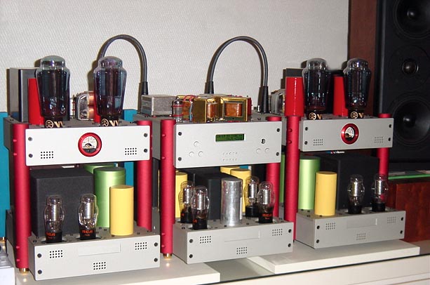
The preamp is the middle one. These aren't mine.
The preamp is the middle one. These aren't mine.
WOW
That is a pretty set up........
Not too sure about the multi coloured design though.....
If the reason for removing the power supply from the amp stage is to remove its potentially damaging effects, would placing them directly underneath really make that much of a difference?
The proximity in those shown must only be 10 cm more than them being in the same chassis...
Take a look at amp (tyco)CPC connectors, there are several variations that include 4 pins, 9 pins and 13 pins that are highly suitable for tube amplifier use. They are not too expensive, and there are a few vendors who even sell them as a package with the pins. (Will look some more and see if I can find one of those vendors.)
Incidentally an interlock connection on the cable or connector such that the supply cannot operate without the cable plugged in is a nice safety feature if you have the extra pins required. This works best in the scenario where the umbilical from the amplifier plugs into the power supply. I actually don't like having 60Hz AC running through my umbilicals if this is not the case.
In pre-amplifier applications particularly it is great to be able to get the noisy power transformer (magnetic fields) and rectifiers away from sensitive low level circuitry.
If you use constant current dc for filament heating as opposed to constant voltage then the voltage drop across the umbilical wiring is not an issue as long as the contacts and wire are sized appropriately for the load current. Note that the current source should have enough voltage compliance (voltage margin on the input side) to handle any of the drops present in the wiring without dropping out under load or low line conditions. Constant current is also gentler on tube filaments during warm up.
Just my opinion..
Kevin
Edit to correct grammatical error.. LOL
kevinkr said:Take a look at amp (tyco)CPC connectors.....
Yep, turns out that's what we use here. Available from Digikey.
Incidentally an interlock connection on the cable or connector such that the supply cannot operate without the cable plugged in ...
Great idea. Do you just route the primary through a connector jumper back into the PS chassis?
After stacks of excellent advice, the only thing I have to add is that with any half-decent multi-core cable (all stranded) heater voltage drop is no problem unless you have a monster of a pre-amp or use it in another room (which you are not). It is perfectly in order to have down to 5V only on 6.3V pre-amp heaters - sometimes even an advantage noise-wise. I have used cords of up to 6m with a total of 1.2A heater current.
- Status
- This old topic is closed. If you want to reopen this topic, contact a moderator using the "Report Post" button.
- Home
- Amplifiers
- Tubes / Valves
- Remote Power Supply: A Stupid Idea?