Hey Guys,
I'm brand new to the site. I've been looking at the EL34 PP amp in the article by Claus Byrith (http://www.lundahl.se/pdfs/claus_byrith/amplifier_30wpp.pdf). Instead of just choosing the same mains transformer as him (Lundahl LL1669A), I wanted to get an "equivalent" tx from Hammond. I've done alot of reading on tube amp design (your "online tube learning for newbies" section is great!!), but there hasn't been alot on sizing mains transformers. From the EL34 datasheets, it looks like a PP pair of EL34s in UL mode could draw up to 150-200mA (so a stereo amp would draw 300-400mA) (I know there are other draws on the HV line, but this is the majority I believe). But Hammond tranies kinda max out a 200-250mA. Now is my 300-400mA estimate way too high (and I need to do more reading), or are Hammond tranies catering to mono-block design?
I'm brand new to the site. I've been looking at the EL34 PP amp in the article by Claus Byrith (http://www.lundahl.se/pdfs/claus_byrith/amplifier_30wpp.pdf). Instead of just choosing the same mains transformer as him (Lundahl LL1669A), I wanted to get an "equivalent" tx from Hammond. I've done alot of reading on tube amp design (your "online tube learning for newbies" section is great!!), but there hasn't been alot on sizing mains transformers. From the EL34 datasheets, it looks like a PP pair of EL34s in UL mode could draw up to 150-200mA (so a stereo amp would draw 300-400mA) (I know there are other draws on the HV line, but this is the majority I believe). But Hammond tranies kinda max out a 200-250mA. Now is my 300-400mA estimate way too high (and I need to do more reading), or are Hammond tranies catering to mono-block design?
For those without high-speed DSL
After downloading the massive 34 page file, the transformer is spec'ed at 350 VCT, 6.3 volts & 130 volts with a 240 volt primary. Using a HV bridge & the center tap for a second lower voltage B+ supply, a full-wave CT circuit is not an option without two transformers.
For a stereo amp I would specify 350 vct @ 600 ma, 6.3 vac @ 8 amp & 130 vac @ 150 ma. The 130 volts is feeding a huge 220uf cap, thus the high current spec of the 130 volt winding.
Hammond does not manufacture any iron that will work. A company in the USA that will manufacture one-offs to spec is Heyboer in the state of Michigan (616) 842-5830. They ship to Canada.
Thanks for the replies. Sorry about the 34 page download. I'm spoiled with a high-speed connection.
I'm more concerned with HOW you guys come up with the current requirements of PP output stages. I haven't found any direct papers or discussions on this topic (but there are alot on single tube class A), so I'm trying to piece it together from articles like the one by Claus Bryith. I don't just want to copy, I want to learn.
So how do you guys calculate HV current required for PP output stages???? Are there any threads that I missed or articles that you guys learned from? Or am I reading the EL34 datasheets correct by saying a PP pair of EL34s in UL mode could draw up to 150-200mA? Thanks.
The input cap size does not dictate the winding current selection....
As the cap gets bigger the PEAK current goes up....but the conduction angle is reduced, therefore the current pulse gets more narrow... ie, smaller Duty Cycle.... The current ratting of the transformer is in direct corelation to it's rise in tempertraure above ambient 25 C.....Since Wattage is with respect to TIME...the ON time of the current pulses are reduced as peak current goes up...The overall Energy remains the same...
The RMS current demand of the PP circuit remains the same...
Chris
Hey Almost!
I just completed my first DIY tube amp and used Heyboer to custom wind my power and output xfrmrs.
Top-notch folks, best customer service BAR NONE and very good iron at a very reasonable cost.
I suggest giving them a call and telling them what you need. I had them wind a 22 lb. monster: 800vct @750ma, 5v@10amps and 6.3vct@10amps. Iron works perfectly and doesn't even reach room temperature-even after a few hours use!
IIRC cost was @ $250.
They also custom wound faithful copies of Dynaco a-420s, 6-60k response and rated for 70 watts. Since during testing after construction they passed an undistorted sine at 4 HERTZ! I think they made a fantastic pair of outputs.
Ask for Alden or Phil.
Best,
mr mojo
mr mojo said:Hey Almost!
Iron works perfectly and doesn't even reach room temperature-even after a few hours use!
That's the correct result....even motors rated at the correct load shouldn't refuse the backhand touch. Towards physics, for best efficency iron losses should equal copper losses and youv'e got that.
You mentioned undistorted sine at 4 Hz....-could you tell us how much power you got out ?
richj
Hey mr mojo
What did you make for your first tube amp? Is it true - does it sound even better when you make it yourself?!?!?!
What info did you give the guys at Heyboer? Did they figure out the specs from your circuit? Or did you have to tell them the voltage/current ratings? If so - how did YOU figure them out?!?!
I've heard of Heyboer a few times on this forum - sounds like great transformers (no pun intended).
Thanks,
almost.
Hey Almost!
Well, I think it sounds better than any Ive heard so far-but then it's safe to say I'm pretty "biased."
Here's some pix:
http://www.diyaudio.com/forums/showthread.php?s=&threadid=64164
Don't be at all afraid of ordering custom iron-that way you get exactly what you want and don't have to make compromises!
As for info they'll need:
They'll need to know mains voltage in. In the US it's 120, but you're in Canada? so I don't know what you folks use.
If you're gonna go stereo rather than mono, then after speccing the mains you need to give them specs for secondaries.
I took a peek at your circuit and if you're building a stereo unit you'll have to power a pair of 5AR4s-just like my amp-dual rectifiers are pretty sweet!
Most of the time the 5AR4 plates run @ 400v, so on the high-voltage secondaries you'll need 800 volts center-tapped.
As for HV secondary current, a pair of 5AR4s can generate @ 300-320ma. IIRC and each pair of EL34s should draw 60ma in PPAB1 or 125-140ma in AB1 UL.
So, you could spec the HV at @ 350ma You'd be OK, but just barely. If you've got the space, money and back muscles, I'd double it.
So, HV secondary becomes 800vct(IIRC 820vct listed on your circuit, but I'd go with 800 so if your mains voltage is a little high, which almost all are, you won't go over the 410v per side-but it's your amp so it's your call!) at a minimum of 350 ma.
7-800 ma would be even better-less sag and better voltage regulation and less heat.
Now, you'll also need a pair of rectifier filaments on another secondary winding as well.
A single 5AR4s filament will draw 5v and 1.9amps. You've got a pair, run in parallel, the 5v stays the same, but the current doubles to 3.8. A safe number would be 5 amps. Once again, rate it higher and it'll run that much cooler.
As for your tube filaments, they're 6.3vct-(in your schematic it's 3.15vct; which you choose depends on how you run your filaments) and 1.5amps per EL34 and .3amps for each ECC83(12ax7) I don't know what the EF88 is rated for.
So, for the current ratings for the tube filaments, simply add 'em up: 1.5(4)+.3(2)=6.6 amps for the EL34s and 12ax7s.
I'd guess the EF88s might be .3 amps like the 12ax7s-but that's only a guess. If so, adding an additional .6amps brings the grand total to 7.2 amps.
I'd go a minimum of 8 amps-bearing in mind the filament amp draw for the EF88s is only a guess.
So, You'd need a power xfrmr with 120 or 220v mains in-depending on what you use in Canada.
800-820vct HV secondary rated at a min. 350ma.
5v rectifier winding at a min. 4 amps.
And a 6.3vct or 3.15vct filament winding at a min. 8 amps(depending on the current draw of the EF88s.)
Unless I missed something on the power xfrmr listed, that's about it.
If you go through Heyboer they'll do a good job of walking you through all this as well.
HTH,
mr mojo
Rich,
Max measure power output was 34.6wpc!
Some pix if you're interested in a peek:
http://www.diyaudio.com/forums/showthread.php?s=&threadid=64164
Best,
mr mojo
Max measure power output was 34.6wpc!
Some pix if you're interested in a peek:
http://www.diyaudio.com/forums/showthread.php?s=&threadid=64164
Best,
mr mojo
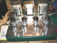
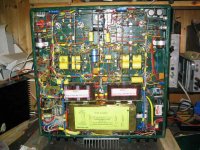
Hi there....I did this woppa 2x 175W amp several years back using switchmode pfc. Weight about 65Kg.
Interesting comparison and complexity when S State B+ is thrown in with also alot of protection circuitry required. This amp used a smaller sized mains tranny (600VA) merely for line isolation.Note absence of tube rectifiers and uses earth busbar circuit.
A massive bonus is dual switched B+ one setting for normal listening Class A 250V+ 30wpc and AB2 530V+ for full 175W....the former ideal for tube longevity. As mentioned a lot of hard nights working took nearly a year bis complete.
Complete digital setup for bias and hosts of other features....Brill performance but Would I do another build , No!
hope pics come through
richj
Attachments
Rich,
That is OUTSTANDING!!! I am humbled and tremendously impressed all at the same time.
Having built a much simpler circuit-but with the same layout and circuit design asthetic as yours-I can truly understand what it took to build that masterpiece.
I'd say there are very few builders in the world able to do that kind of work. I can only hope to get there one day myself.
Wow. I wish I could say something more profound, but I'm too stunned. Wow!!!
Rich, if you've got some time and don't mind me taking up some of it, I'd sure enjoy asking you some questions by e-mail about your build.
Sorry for the hi-jack, Almost-but that thing deserves recognition!
Best,
mr mojo
:- Mojo
This bit of preamble is also for others to read....when one builds a tube amp one has to decide keeping matters simple i.e how much power one is after and type of topology, but when one enters the real power game, designs require more thought.
This 2x175W tube amp audio circuit design itself (as you know) doesn't consume much brain time....some research was done on getting the performance of the drivers right which after alot of josling I ended up with good ECL82's strapped as triodes....sloppy gain but ideal low thd Z Miller dump characteristics for o/p stages....requires p-p driver stages sucking 35mA at 360V. (sep B+)
...in the case of using solid state en force... it's all the subsidary safety circuits that take time....... I did the pfc (in biscuit tin) using surface mount (smd).
I would advise anyone using smd on standard pcb to solder a bit of reinforcing pcb (edgeways as a stiffner across back) to avoid any possibility of bending. This is important with pfc or other designs as a broken joint/component spells immediate disaster.
This high power supply firing AB2 has to supply at least 1 ampere at 530V without sagging so it won't budge if a tube goes down, and with fixed bias some sort of interlock is required to avoid meltdown. Fuses in each o/p tranny primary is essential to avoid permanent damage. It's this and other watchdog circuits that complicate issues. As a system designer, the step into the realms of true power supply design can be challenging when every fault condition has to be allowed for. The simplicity of the standard EL84 /34 design has alot going for it and cannot be overstated and walking into pfc design is more than a high wire act.
Understanding this stuff is fine but so often reads on other threads the interference problems gets many bogged down. unfortunately solved emc over forums cannot be done without proper RF experience. Putoff ?
The bit I would really like to mention is the attractivity of the class A parallel p-p pairs condition at 30W per channel with reduced B+ of 250V allows so many tubes to be used from 6L6's 5881's + KT's in fact the whole power pentode class and with great longevity. For HiFi this amp can deliver poke.....But a lock and key is required so one doesn't accidently fire up fledglings on board with 530V .
Some might notice the 600VA tranny is small, isn't really as pfc tracks true rms so one can use one size down. The use of a mains transformer isn't novel.....remember heater supply for 8 power tubes will suck nearly 100W and other smaller tubes down chain can be ignored but the tranny simplifies heater juice and also the interstage B+ 360V . ....
For trumpet powers I use solely KT88's to make a noise but many have tried this amp with guitar without feedback (16dB) and like different combinations of o/p tube.
What I've really ended up is the same as the Mesa boogie but not so flexible.
Quick Anon---more later
richj
mr mojo - thanks for the detailed reply. You've clarified alot for me. It finally got me over a little hump and I was designing all night!
And your amp looks incredible. I wire electrical panels for a living, so I appreciate how much extra work it must have taken to get the wiring so neat. Truly outstanding. Did I read right? International Harvestor Red?!!?!? Awesome idea. It really stands out of the pack.
And your amp looks incredible. I wire electrical panels for a living, so I appreciate how much extra work it must have taken to get the wiring so neat. Truly outstanding. Did I read right? International Harvestor Red?!!?!? Awesome idea. It really stands out of the pack.
Rich - I see how that could take a year!!!! I quickly contemplated a switching power supply, but it seems like a project in itself. I bet you learned a ton building this amp. Glad to see it paid off.
Don't worry about hi-jacking a thread when you guys show off amps like these!!!! I love to see the capability of the guys on this forum.
Almost
Don't worry about hi-jacking a thread when you guys show off amps like these!!!! I love to see the capability of the guys on this forum.
Almost
AlmostGotIt said:
So how do you guys calculate HV current required for PP output stages???? Are there any threads that I missed or articles that you guys learned from? Or am I reading the EL34 datasheets correct by saying a PP pair of EL34s in UL mode could draw up to 150-200mA? Thanks.
I've used plenty of Hammond transformers in stereo push-pull setups with no problem.
Some common sense things to think about...
You will not be listening to music at full power all the time.
I shoot for a B+ voltage of about 425-450V to get you a power output level of at least 30W.
Don't bother running EL34's static (idle) plate power levels higher than 20W. 450V/20W = 44.4mA. I personally run EL34's at 35-40mA.
The current spec. on a transformer is what the wire is rated at. It is usually assumed you will use the transformer in the center-tapped configuration. Doing so means you are using the secondary in two half-wave circuits, think about it. Each of which only conducts for a half-wave. Each half-bridge circuit AVERAGES only half the current which means you can pull double the amount of current out of the transformer to meet the wire current spec. If you use the secondary as a whole, then you cannot do this.
So let's say your stereo circuit is consuming 200ma on average. Each secondary half wave section sees 200ma for a half wave and then 0ma for the other half wave... (200ma + 0ma) / 2 half cycles = 100ma for the average. Each half wave section alternates between each other while conducting, one conducts for a half cycle then the other. Why? Because one section is 180 degrees out of phase with respect to the other since it is wound on the core upside down with respect to the CENTER TAP.
Hammonds are known to be conservative with their ratings. I'm certain you can build a nice performing stereo EL34 amp with a hammond transformer rated at 200-250mA, I've done it many times!
Just an important reference point that alot miss...I know this isn't really the thread for this but since I mentioned the topic in a reply ...When designing smps for audio amps .. the beast is a massive HF switching radiator and the present class B FCC emission limit curves go up/down and step slightly at around 100MHz....but look at the permitted emitted level around 35dBuV/meter assumed into 50 ohms. This represents a basic voltage front of 57uV or -72 dBm at 30 meters. When one looks at the front end of a good FM tuner with a loose wire aerial, that sensitivity starts typ under 10uV and requires appreciably more than that for limiting the discriminator. Under limiting conditions any interference will have a hard time getting through but it shows that by putting an FM tuner in the same rack with equipment using a smps, one will have a tough time with weak reception (worst case with a poor aerial). In the real world the same effect and happens with a CD player. I can't use my FM tuner with the CD player simply switched on. Simply because it's impossibe on cost grounds for manufacturers to put a screw on every bit of sheet metal.
I'm a bit out of date with current emissions tolerance and pollution specs but unless these smps are put in biscuit tins with proper feedthrough's and filters one has a chance but as the power goes up so does the emissions. There are ways with different topologies to reduce the harmonics, and also the different approvals houses around the world also have differing specs, but in staying with tubes thread any further comment really belongs to the power supply forum.
I never like to criticize tryer's out with smps ( it's excellent multi facetted intitutive physics) but double sided pcb's with a ground plane is really the only proper approach.
Genug
richj
Gilbert - thanks for the reply.
Alot of my confusion comes from past designs that spec different size tranies. For example, the Dynaco Stereo-70 is a Push-Pull EL34 which uses the PA-060. That seems to be rated ~250-300mA for the B+. But then I heard that it was the weak point in the system. So my confusion continued.
Can you check my reasoning here:
1 channel with 2 EL34s in PP UL (43%). Bias set to 40mA. Therefore the channel draws a constant (2x40mA) 80mA with no signal input. According to the EL34 datasheet for this config, a 35Vrms(g1-g1) input signal will output 20W and cause the EL34 pair to draw (2x62.5mA) 125mA plus (2x10mA) 20mA into G2. THEREFORE, I assume that when play the channel at 20W output, the channel will draw 125mA+20mA = 145mA. This seems to match what mr mojo said.
Am I right in how I came up with this number? How can a tranny rated a 250mA supply 2-channels drawing 145mA each? Is the 145mA not a constant draw (ie) 145mA is the just peak value of the wave, or only attained when you have the thing at full output?
Thanks!
Almost
AlmostGotIt said:Gilbert - thanks for the reply.
Alot of my confusion comes from past designs that spec different size tranies. For example, the Dynaco Stereo-70 is a Push-Pull EL34 which uses the PA-060. That seems to be rated ~250-300mA for the B+. But then I heard that it was the weak point in the system. So my confusion continued.
Yeah, so what?
Can you check my reasoning here:
1 channel with 2 EL34s in PP UL (43%). Bias set to 40mA. Therefore the channel draws a constant (2x40mA) 80mA with no signal input. According to the EL34 datasheet for this config, a 35Vrms(g1-g1) input signal will output 20W and cause the EL34 pair to draw (2x62.5mA) 125mA plus (2x10mA) 20mA into G2. THEREFORE, I assume that when play the channel at 20W output, the channel will draw 125mA+20mA = 145mA. This seems to match what mr mojo said.
Yep, resonable enough, but a 20W continuous power level is pretty loud. The meters on my McIntosh indicate that I listen to an average of 10W continuous and that is fairly loud given a relatively efficient speaker.
Am I right in how I came up with this number? How can a tranny rated a 250mA supply 2-channels drawing 145mA each? Is the 145mA not a constant draw (ie) 145mA is the just peak value of the wave, or only attained when you have the thing at full output?
Go back and reread what I wrote about using a power transformer in a center tapped configuration. Used in this way, which is the most typical way, you can pull twice the amount of current out because you are using the secondary in TWO HALF WAVE circuits, which alternate between each other. For one secondary circuit you can pull say 200ma for a half wave and then 0ma for the other half wave and average 100ma (200 + 0)/2. The other secondary circuit alternates this pulling 200ma when the other circuit is at 0. So each half wave circuit *averages* 100ma while pumping 200ma into your load.
Does that help? If you pay more than $100 on a power transformers, well...ok, but if you spend more than about $150 on one than your spending more than you need to IMO.
The following are from the Anitque Electronics Supply site, I've used the second one to build a stereo 6L6 based amp that sounded fantastic. Even when running the 6L6's a little cool at 18-20W, about 35ma each. You can do it fairly cheaply using off the shelf transformers.
TRANSFORMER, POWER, FENDER REPLACEMENT, 335-0-335 V, 450 mA @ $73.50 This would do quite nicely for just about anything and give you enough B+ for an easy 40W.
TRANSFORMER, POWER, HAMMOND, 300-0-300 V, 250 mA @ $64.95
TRANSFORMER, POWER, HAMMOND, 400-0-400 V, 465 mA @ $79.95 Plenty of current but will result in high B+ voltages.
Thanks!
Almost
- Status
- This old topic is closed. If you want to reopen this topic, contact a moderator using the "Report Post" button.
- Home
- Amplifiers
- Tubes / Valves
- Mains Transformer for EL34PP