Would one of you please proofread this article for me. I wanted to put together an explaination of cascode circuit design in plain terms for DIY guitar amp builders, and I want to make sure it is not off base anywhere. I'll add you guys in the credits as editors if you want.
http://www.geocities.com/keirkegeerd/cascodesforthebuddingdiyer.pdf
Thanx a million for all your help!!!!!!
http://www.geocities.com/keirkegeerd/cascodesforthebuddingdiyer.pdf
Thanx a million for all your help!!!!!!
It's the input resistance of the following stage in combination with the coupling capacitor that sets the low-frequency roll-off. That's why self-bias cathode followers can get away with such tiny input coupling capacitors.
Can I suggest that you let a spell-checker loose on your text, also that you practice using the shift key on things like "ECC88" but use lower case "k" for "kilo" because "K" is short for "Kelvin" (the unit of absolute temperature).
Can I suggest that you let a spell-checker loose on your text, also that you practice using the shift key on things like "ECC88" but use lower case "k" for "kilo" because "K" is short for "Kelvin" (the unit of absolute temperature).
The article seems not regimented...There does not seem to be a structured design process....It seems to be a lets try this and lets try that and see where the numbers lead us....
I guess that works for musicians but that would not fly in the engineering environment....
Rp, gm...ect.. Are determined based on the operating point choosen...not from the numbers given in the data sheet, unless you operate at the same conditions as stated in the data sheet.
As for the origins of the ciruit.... You can call it a TRANSIMPEDENCE amplifer..... The top triode is acting as a voltage regulator...actually a cathode follower voltage regulator...
It is passing along the AC signal current to the load at the very top...in that sense it is gm.... To qualify as a gm amp you would have to come up with bigger numbers for the effective output resistance....
Chris
HA. Yeah, I didn't spell check it yet, I wanted to make sure that the math was cool first. Thanx for all the replies. I would not presume to be able to write anything on en engineering level, but I want to help guitar amp guys understand this stuff a bit better...hence the slang and fun language. I also chose operating points that would get me some results close to a typical gain stage in a guitar preamp to, so that's why the numbers are a bit wacky.
-("...It's the input resistance of the following stage in combination with the coupling capacitor that sets the low-frequency roll-off. That's why self-bias cathode followers can get away with such tiny input coupling capacitors...")
I have that math in there. In the other section I was referring to the effects of a the Ck capacitor in regard to a partially bypassed cathode resistor as a treble peaking circuit.. guitar amp guys call that the frequency response of a stge, but I don't know if that is right. You are right about the lower case K too, I was just being lazy with the shift key.
-("Rp, gm...ect.. Are determined based on the operating point choosen...not from the numbers given in the data sheet, unless you operate at the same conditions as stated in the data sheet.")
...yeah...I know. i had a heck of a time finding a set of curves for any modern tube that show transconductance at a given operating point. I found one for a 6dj8 and used that to estimate. I found a runup that Steve Bench did on a 6H30 too, which was cool. I found a few 'rule of thumb' formulas for Gm, but nothing solid... lots of mystery out there. BUT, are you saying that a textbook cascode is not a gm amp? That I do not understand.
Thanx again!!
Sorry..
I re-read the article and now see the proper equation I did not see before.... It was the Zo equation.... which is correct... So yes I do now agree with you about seeing it as a gm amp based on the equations in your article...
Personally, I got lost in all the clutter...I prefer just a paragraph explaining functionality of the circuit and another few paragraphs showing derivation of equations....then a final cleaned up version of the essential equations.....
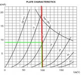
I did get confused with the RED line that is drawn in plate curves graph???? The lower cascode "idealy" sees no load on top and should be "locked in" at a set plate voltage ..so there should be no signal movement at the plate of the lower valve...therefore the movement should be strictly VERTICAL on the graph, behaving in accordance to gm....you can see the spacing is horrible when moving VERTICALLY with this triode, worse than a pentode...this radical delta in gm will fuel harmonics ...which is great for guitar.... As we all know , in real life there is a finite impedence looking into the top triode from the bottom triode's perspective... thats why I use an active negative feedback from that node to the upper triode grid.... This effectively lowers the looking in impedance of the upper triode..and now you approach ideal Gain.... A lot of trouble for little more improvement....
Chris
I re-read the article and now see the proper equation I did not see before.... It was the Zo equation.... which is correct... So yes I do now agree with you about seeing it as a gm amp based on the equations in your article...
Personally, I got lost in all the clutter...I prefer just a paragraph explaining functionality of the circuit and another few paragraphs showing derivation of equations....then a final cleaned up version of the essential equations.....
I did get confused with the RED line that is drawn in plate curves graph???? The lower cascode "idealy" sees no load on top and should be "locked in" at a set plate voltage ..so there should be no signal movement at the plate of the lower valve...therefore the movement should be strictly VERTICAL on the graph, behaving in accordance to gm....you can see the spacing is horrible when moving VERTICALLY with this triode, worse than a pentode...this radical delta in gm will fuel harmonics ...which is great for guitar.... As we all know , in real life there is a finite impedence looking into the top triode from the bottom triode's perspective... thats why I use an active negative feedback from that node to the upper triode grid.... This effectively lowers the looking in impedance of the upper triode..and now you approach ideal Gain.... A lot of trouble for little more improvement....
Chris
Yeah, I did ask elsewhere on this forum about plotting a line for the bottom tube when I realized that it should start around 300mA for the circuit I used... almost a ******** straight line. CRAP!!! You are right...I forgot to change that paragraph, good call.
By active feedback, are you referring to a self bias configuration, where the top tube's grid is tied to the bottom tube's anode?
Maybe I'll redo the article so that it is more step by step. If the experts can't follow my jumbled mess, then how can I axpext a noob to?
Tell me, is this chart a better representation of the operating point:
Attachments
One more thing
I know the formula gm=dIp/dVg, BUT is there any way to figure out what the gm of a tube will be at a particular bias point without plotting it on a dynamic curves sheet? OR BETTER YET. Does anyone have a graph of a 6922/6dj8/e88cc/6h30 that shows the curves for gm against current?
I know the formula gm=dIp/dVg, BUT is there any way to figure out what the gm of a tube will be at a particular bias point without plotting it on a dynamic curves sheet? OR BETTER YET. Does anyone have a graph of a 6922/6dj8/e88cc/6h30 that shows the curves for gm against current?
As long as the cathode resistor is bypassed..then the RED line is the slope representing 1/gm of the top valve.....
I have the gm curves for a 6922 ...but not with me... There is a book that has them...maybe someone here can help with that..
As for active feedback.....I am refering to using an inverting op-am in the feeback loop between the lower anode and the upper tubes grid...while still maintaining the DC reference voltage...
Chris
cerrem said:As long as the cathode resistor is bypassed..then the RED line is the slope representing 1/gm of the top valve.....
I have the gm curves for a 6922 ...but not with me... There is a book that has them...maybe someone here can help with that..
As for active feedback.....I am refering to using an inverting op-am in the feeback loop between the lower anode and the upper tubes grid...while still maintaining the DC reference voltage...
Chris
INVERTING OPAMP! Brilliant. I would never have thought of that.
1/gm for the slope eh? I guess for a rule of thumb, I could use a straight line since 1/12,500 is off the chart anyway.
I think what I need to do is invest in a book of complete tube curves. Last night I actually found a 36 page PDF from Phillips that has all the curves I need, INCLUDING a graph for a 6922 in cascode... boy would that have made life easier

- Status
- This old topic is closed. If you want to reopen this topic, contact a moderator using the "Report Post" button.
- Home
- Amplifiers
- Tubes / Valves
- Could you guys check this cascode article for me