Hey Glenn,
Nice work so far! I just finished my first DIY amp and ended up with something like 126 holes, so I can appreciate the time, patience and care it takes to drill a lot of holes and keep them symmetrical and even.
Great work on the turret board as well-I always like to see folks taking just as much care under the amp as on top!
As for your wiring layout, I'm with Sherman on the single ground point on the chassis and separate dedicated grounds for each componant running back to it.
It's my understanding that there should be only a single point grounded to chassis. If you have multiple ground points on the chassis that can lead to ground loops since each of those points on the chassis can be at slightly different potentials as referenced to ground-the definition of a ground loop.
I've talked with other builders who've used the method you described without issue, so it can and does work fine-but for the absolute best chance of lowest hum a single ground point is recommended.
And since separate "clumps" of localized grounds going back to a single ground point is used to approximate a true star ground for reasons of convience, space and time, I'd go for a true star ground since you're not bound by any of these constraints . I used this solution on mine and I've got ZERO hum-even with the amp at full volume.
Also, according to the "Amatuer Ham Radio Operators Handbook" circa 1969, the length and position of the power supply leads-as long as they are tightly twisted and run close to the chassis-is of little importance. What IS more important is that there are no exposed or sloppy connections or wiring that can be touched or short to chassis or other componants.
Best,
mr mojo
Thanks Mr. "M"
Yes, I'll be playing around with a few different wire routings I'm sure as I go along
I just finished all of the wiring with the exception of the OT's as I don't have them yet.
Funny how money always creeps into these projects
530VDC on the B+ without any tubes!!!!
Here's the amp so far:
http://webpages.charter.net/porkchop/tubeamp/IMG_0270.jpg
http://webpages.charter.net/porkchop/tubeamp/IMG_0271.jpg
http://webpages.charter.net/porkchop/tubeamp/IMG_0272.jpg
http://webpages.charter.net/porkchop/tubeamp/IMG_0273.jpg
http://webpages.charter.net/porkchop/tubeamp/IMG_0275.jpg
http://webpages.charter.net/porkchop/tubeamp/IMG_0276.jpg
http://webpages.charter.net/porkchop/tubeamp/IMG_0277.jpg
http://webpages.charter.net/porkchop/tubeamp/IMG_0278.jpg
http://webpages.charter.net/porkchop/tubeamp/IMG_0279.jpg
Nice work Glenn-you're well on you're way to building a "keeper" to be proud of for sure.
Great paint on top as well, that gold and silver combo is killer.
With a layout and implementation that clean, tidy and well thought out I'd bet a whole lot of money you'll have no issues at all. I think I get even more excited by the underside than the top, and your work is definately something to get excited about.
Now, go on and wire that thing up however you like and don't pay any attention at all to me-it's obvious you know what you're about under the amp!
Really, really nice.
Best,
mr mojo
Thank you sir for the compliment!
I've only been doing this for <2 years, but I've learned so much from everyone on this forum.
I'm also an avid antique radio collector/restorer so this is pretty straight forward compared to some radio circuits.
I guess I'm one of those "Anal-types" so I'm very picky about my projects.
I'm looking forward to completing this. It was a departure from all my other amps in that it's not a PP design. I've never built an SE amp before, but all my radios use this type of output stage. I just hope the UL SE sounds better than some radios
I'll keep posting new pix as I progress further. Now I just have to talk the Wife into a $200 purchase of output transformers!
Glenn
porkchop61 said:Thanks!
I was just looking at Sherman's build, and it looks like he doesn't have an additional wire to ground. Maybe he does't need it if he has no hum, Sherman?
Glenn
Glenn,
No, I didn't run a ground wire from the binding post to chassis ground. I have no audible hum with 89dB/1W/1M speakers but if I put my ear within about a foot I can hear a small bit of hum with 94dB/1W/1M.
I've been thinking about putting one in just to see if there is a difference but it hasn't bothered me enough to try it yet!
porkchop61 said:Yes, I think I'll just see how it sounds and go from there.
I do add a ground wire to all my guitar amps output jacks, and so far no hum in any of those.
The carbon resistors do hiss nicely in one amp I have though
Glenn
Now I am curious. When I get a chance later today I'll just clip a test lead from the black binding post to the main ground point as see if I can hear a difference.
That's the nice thing about DIY, we can always change it (or at least incorporate changes in the next version
).Here is the PS I use. It is very quiet and works well. I am getting about 425V on the B+ so there is sufficient voltage for an additional RC filter after the 100uF cap if desired.
My amps are set up as monoblocks but the only change needed for stereo is a beefy enough power transformer. My KT88s are biased at about 82mA and the 6N1P draws about 10mA (IIRC, its been a while since I measured it). So a power transformer capable of about 200mA would be OK.
My amps are set up as monoblocks but the only change needed for stereo is a beefy enough power transformer. My KT88s are biased at about 82mA and the 6N1P draws about 10mA (IIRC, its been a while since I measured it). So a power transformer capable of about 200mA would be OK.
Attachments
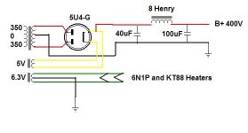
matthew2456 said:out of interest where did you get your 8H choke from?
Thanks
I got all my Hammond iron from Angela Instruments (www.angela.com). For my amps I used Hammond power transformers and Hammond chokes.
For output transformers I used James 6123Hs from Euphonia Audio.
porkchop61 said:Thanks Mr. "M"
Yes, I'll be playing around with a few different wire routings I'm sure as I go along
I just finished all of the wiring with the exception of the OT's as I don't have them yet.
Funny how money always creeps into these projects
530VDC on the B+ without any tubes!!!!
Here's the amp so far:
http://webpages.charter.net/porkchop/tubeamp/IMG_0270.jpg
http://webpages.charter.net/porkchop/tubeamp/IMG_0271.jpg
http://webpages.charter.net/porkchop/tubeamp/IMG_0272.jpg
http://webpages.charter.net/porkchop/tubeamp/IMG_0273.jpg
http://webpages.charter.net/porkchop/tubeamp/IMG_0275.jpg
http://webpages.charter.net/porkchop/tubeamp/IMG_0276.jpg
http://webpages.charter.net/porkchop/tubeamp/IMG_0277.jpg
http://webpages.charter.net/porkchop/tubeamp/IMG_0278.jpg
http://webpages.charter.net/porkchop/tubeamp/IMG_0279.jpg
WOW!!!! That looks REALLY nice. I wish I could afford to complete mine soon. Im a bit ashamed I haven't already completed it. But these things should not be rushed.
matthew2456 said:would a 47uf cap suffice in the powersupply rather than a 40uf as i happen to have one lying around
47uF would probably be OK, most caps have quite a tolerance range. Just be careful if you are using tube rectification. I'm using 5U4G rectifiers and they are rated for a maximum of a 40uF cap in a cap input supply. When using cheap Chinese tubes I had some sparking internally. I replaced them with Sovteks which have been working fine for over a year.
If you see sparks inside your rectifier tubes change the first cap to something smaller.
- Status
- This old topic is closed. If you want to reopen this topic, contact a moderator using the "Report Post" button.
- Home
- Amplifiers
- Tubes / Valves
- Stereo build- Mikael Abdellah's KT88 SE amp