Well, before I get to the good stuff I would like to give a very big tip of the hat to PRR without whom this amp would not be working.
Before I get started a brief overview of how I got here:
About 6 years ago I came across an old "Rolling Stone" article about building a 10 grand stereo system for less than 2. The amp suggested was a Scott 299C. Since I was a college student at the time I had neither the time or money to pursue such a project, but I wanted to.
Got my first job out of college 3 years ago and after working for a year decided it was time to tackle a Scott 299C. At the time my knowledge of electronics started and stopped with the "on" button.
With a lot of help from some patient folks at audiokarma, I got that Scott up and running, and boy was I hooked!
Next came a 299B restoration for a friend. Then a mint 296 came up for sale on ebay less than 4 hours from me. About mid-way through that restoration I thought, boy this is getting to be a pain in the ***.
Wouldn't it be nice to not take something out, clean the pins, just to put a new part in, all the while fighting all the other parts already there?
Just like that the idea of a DIY tube amp was born. Since I enjoyed the sound of the 299C better than any other tube amp I'd heard up to that point-and had the outputs from my rather dog-eared example to use-I decided to buy one of those articles you see on ebay all the time-"Build your own 20 watt EL34 amp!", "Build your own 60 watt KT66 amp!"
I, of course, chose the "Build your own 35 watt 7591 amp!."
Schematic arrived, and on first look I thought, "Wow, am I ever screwed."
Circuit uses 7591s in PP, dual 5AR4s for power, dual 0A3s for screen regulation, a pair of 6AN8s for gain/phase splitting and has bias adjustment for each channel as well as test points and trimmer pots for DC and AC balance of each channel.
Ordered a custom pwr xfrmr from Heyboer since I couldn't find one commercially made big enough. Scematic lists an 800vct@340ma, 6.3vct@5 amps and 5v@4 amps.
I had Heyboer wind a monster 800vct@750ma, 6.3vct@10 amps
and 5v @ 10 amps. What can I say, I wanted to avoid sag and heat.
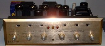
Got a steel chassis from hammond, ceramic sockets, carbon film resistors and separate Sprague Lytics instead of multi-section cans. Terminal strips are turret-type from IAG and the volume pot is a custom dual 500k stepped attenuator from Shalco-30 steps, make before break, 1.2 db steps.
After drilling most of the holes in the chassis, I found the primary and secondary leads of the Scott outputs were all cracked from heat and age, just outside the core and inside the endbells. After a few attempts at repair, I decided I didn't want to start the project in such a half-assed way, so back to Heyboer I went.
After 3 months and 3 failed attempts at reverse-engineering some outputs to fit the holes I already drilled, I gave up and had them wind some copies of Dynaco A-420s, 6-60k response, fully interleaved, but 1/2" taller and 1/2" deeper to give ma a 70 watt rating.
After another 6 weeks I got my outputs, ordered a new chassis and started drilling from scratch. Since I live in an apartment, the tools I had at my disposal were a hammer, a pin-punch, drill, bits, step up bit and a tape measurer. With all the pounding of the punches, the noise of the drill and the screaming of the step up bit I could only work for about 2 hrs each night before it got too late for such noise.
I started getting strange looks from my neighbors as we passed in the hallway.
After the metal work was done, it was time for paint. Let me say this, unless you are a professional painter let a professional handle it. Just skip the 3 botched attempts at painting, stripping, re-painting and eventual sandblasting to remove the caked layers of paint from the chassis.
After powdercoating the chassis and end-bells I spent the next 3 months assembling, dissassembling, re-assembling, looking dejectedly inside the amp and thinking of all the other things I could've spent my money on instead.
Like a trip to Disneyland. Or hair restoration since mine had grown alarmingly thin and seemed to be visably jumping out of my head as I shaved in the morning.
Then, about a week ago, it was time to fire it up. Plugged in the 7591s and 6AN8s and got so excited about seeing them glow I plugged in the 5AR4s and 0A3s before setting the bias.
PRR helped me understand why I had such an amazing light show and blew my B+ dropping resistor, two of my cathode resistors and the pair of 7591s in that channel. Not really the start I was hoping for.
By Thursday of this week I had the amp repaired and this time got smart and enlisted the help of our only local tube tech and all-around smart guy to help me bring it up.
Still reading? Your either very dedicated or very bored. Either way, now we get to the good stuff.
Square wave response was perfect from 20-20k,+/- 1db and zero overshoot. And these were multiple readings from 20, 500, 1k, 5k, 10k, and 20k as well as each at 5w, 10w, 20w and 30w. In fact all we had were offset parallel lines at the top and bottom of the waves, verticle lines dissappeared. When overlapped each channel matched exactly.
Max power output measured 34.6w.
When switching to sine wave we were able to pass a perfect sine all the way down to 4hz.
Power supply showed absolutely minimal grunge. Article states less than 1% ripple and 86db noise floor. Since we got zero hum at full volume even with our ears on the speaker cones we assumed we're likely close to that.
As for how it sounds, well I may be "biased" but I think it's the most amazing amp I've heard yet. I'll be listening over the weekend and will post my thoughts as well as some pics on Monday.
For now, I'm extremely pleased. And I will say after this project, I don't care if a person builds a SET, PP, class A or class AB amp, be it from a kit or scratch built, if you're dedicated, crazy, talented enough to build it you have my respect and admiration.
Thanks to you if you've read this far, and thanks to all who have helped answer all my silly questions.
I'm out of town for the weekend, but will be taking the amp with me. I won't be able to respond untill monday, but when I do I'll have pics and impressions to share. This project has meant a lot to me and I'd surely appreciate anyone's thoughts and responses on the matter.
One last thing-TUBES F'ING ROCK!
Best,
mr mojo, or John to my friends. Or as my Dad is fond of calling me, jackass.
Before I get started a brief overview of how I got here:
About 6 years ago I came across an old "Rolling Stone" article about building a 10 grand stereo system for less than 2. The amp suggested was a Scott 299C. Since I was a college student at the time I had neither the time or money to pursue such a project, but I wanted to.
Got my first job out of college 3 years ago and after working for a year decided it was time to tackle a Scott 299C. At the time my knowledge of electronics started and stopped with the "on" button.
With a lot of help from some patient folks at audiokarma, I got that Scott up and running, and boy was I hooked!
Next came a 299B restoration for a friend. Then a mint 296 came up for sale on ebay less than 4 hours from me. About mid-way through that restoration I thought, boy this is getting to be a pain in the ***.
Wouldn't it be nice to not take something out, clean the pins, just to put a new part in, all the while fighting all the other parts already there?
Just like that the idea of a DIY tube amp was born. Since I enjoyed the sound of the 299C better than any other tube amp I'd heard up to that point-and had the outputs from my rather dog-eared example to use-I decided to buy one of those articles you see on ebay all the time-"Build your own 20 watt EL34 amp!", "Build your own 60 watt KT66 amp!"
I, of course, chose the "Build your own 35 watt 7591 amp!."
Schematic arrived, and on first look I thought, "Wow, am I ever screwed."
Circuit uses 7591s in PP, dual 5AR4s for power, dual 0A3s for screen regulation, a pair of 6AN8s for gain/phase splitting and has bias adjustment for each channel as well as test points and trimmer pots for DC and AC balance of each channel.
Ordered a custom pwr xfrmr from Heyboer since I couldn't find one commercially made big enough. Scematic lists an 800vct@340ma, 6.3vct@5 amps and 5v@4 amps.
I had Heyboer wind a monster 800vct@750ma, 6.3vct@10 amps
and 5v @ 10 amps. What can I say, I wanted to avoid sag and heat.
Got a steel chassis from hammond, ceramic sockets, carbon film resistors and separate Sprague Lytics instead of multi-section cans. Terminal strips are turret-type from IAG and the volume pot is a custom dual 500k stepped attenuator from Shalco-30 steps, make before break, 1.2 db steps.
After drilling most of the holes in the chassis, I found the primary and secondary leads of the Scott outputs were all cracked from heat and age, just outside the core and inside the endbells. After a few attempts at repair, I decided I didn't want to start the project in such a half-assed way, so back to Heyboer I went.
After 3 months and 3 failed attempts at reverse-engineering some outputs to fit the holes I already drilled, I gave up and had them wind some copies of Dynaco A-420s, 6-60k response, fully interleaved, but 1/2" taller and 1/2" deeper to give ma a 70 watt rating.
After another 6 weeks I got my outputs, ordered a new chassis and started drilling from scratch. Since I live in an apartment, the tools I had at my disposal were a hammer, a pin-punch, drill, bits, step up bit and a tape measurer. With all the pounding of the punches, the noise of the drill and the screaming of the step up bit I could only work for about 2 hrs each night before it got too late for such noise.
I started getting strange looks from my neighbors as we passed in the hallway.
After the metal work was done, it was time for paint. Let me say this, unless you are a professional painter let a professional handle it. Just skip the 3 botched attempts at painting, stripping, re-painting and eventual sandblasting to remove the caked layers of paint from the chassis.
After powdercoating the chassis and end-bells I spent the next 3 months assembling, dissassembling, re-assembling, looking dejectedly inside the amp and thinking of all the other things I could've spent my money on instead.
Like a trip to Disneyland. Or hair restoration since mine had grown alarmingly thin and seemed to be visably jumping out of my head as I shaved in the morning.
Then, about a week ago, it was time to fire it up. Plugged in the 7591s and 6AN8s and got so excited about seeing them glow I plugged in the 5AR4s and 0A3s before setting the bias.
PRR helped me understand why I had such an amazing light show and blew my B+ dropping resistor, two of my cathode resistors and the pair of 7591s in that channel. Not really the start I was hoping for.
By Thursday of this week I had the amp repaired and this time got smart and enlisted the help of our only local tube tech and all-around smart guy to help me bring it up.
Still reading? Your either very dedicated or very bored. Either way, now we get to the good stuff.
Square wave response was perfect from 20-20k,+/- 1db and zero overshoot. And these were multiple readings from 20, 500, 1k, 5k, 10k, and 20k as well as each at 5w, 10w, 20w and 30w. In fact all we had were offset parallel lines at the top and bottom of the waves, verticle lines dissappeared. When overlapped each channel matched exactly.
Max power output measured 34.6w.
When switching to sine wave we were able to pass a perfect sine all the way down to 4hz.
Power supply showed absolutely minimal grunge. Article states less than 1% ripple and 86db noise floor. Since we got zero hum at full volume even with our ears on the speaker cones we assumed we're likely close to that.
As for how it sounds, well I may be "biased" but I think it's the most amazing amp I've heard yet. I'll be listening over the weekend and will post my thoughts as well as some pics on Monday.
For now, I'm extremely pleased. And I will say after this project, I don't care if a person builds a SET, PP, class A or class AB amp, be it from a kit or scratch built, if you're dedicated, crazy, talented enough to build it you have my respect and admiration.
Thanks to you if you've read this far, and thanks to all who have helped answer all my silly questions.
I'm out of town for the weekend, but will be taking the amp with me. I won't be able to respond untill monday, but when I do I'll have pics and impressions to share. This project has meant a lot to me and I'd surely appreciate anyone's thoughts and responses on the matter.
One last thing-TUBES F'ING ROCK!
Best,
mr mojo, or John to my friends. Or as my Dad is fond of calling me, jackass.
I'm listening to my 299C as I write this note.
I also own an HH Scott model 208 power amplifier.
Sadly, the 208's power transformer quit. I purchased a new tranny from Heyboer and installed it in the 208. I upsized the tranny as you did.
When I purchased a replacement tranny for my model 208, I also purchased one for the 299C. I haven't needed the power transformer yet but it's nice to know that I have one if the tranny in the 299C fails.
Enjoy your amplifier. I'll bet it sounds great!
Attachments
How hard can DIY be?
Now you know.
Topping a vintage Scott was ambitions for a first project in an apartment. You get this week's award for persistence.
In retrospect: it would have been fun to start with a dry board, some sockets, some low-price iron, and some brass tacks. Nail the sockets to the board. Hay-wire the resistors etc. Brass tacks can be used as tie-points. Wood is no good for high voltage or high impedance, but a 6SN7/6V6 SET will work just fine nailed into the wood. This makes some learning-steps, like biasing-fires, go faster and with less pain. You can have sound in a few evenings. And because it is all your own handiwork, sweat, and bloodstains, it WILL sound terrific (after you get it to stop smoking).
That's about how Scott et al did their prototyping, except they probably had an old steel chassis with a dozen sockets and a hundred tie-points that they recycled from project to project.
Then a different project would be a source switch and a volume pot (no electronics) in a very-very pretty case. This is a very different set of problems, as you learned. More akin to fine car-body work than electronics.
I can wire stuff, on wood or on PCB. I have proven many times that I can not make it pretty: my projects look like bombs, and bombs that probably won't even work. Unabomer did better mechanical work than I do (but he had more time and no neighbors to complain).
I'm curious as to how you got that "perfect" square wave at the extremes???
My EL84 amp has a kick-<edited> sound but displays a slight bass weakness from about 80 Hz down (believe me, listening to it bass is tight and deeeeeeeeeep) while from about 15K up tends to curve the square wave some... yet the sine is pretty and flat from 10 to 35Khz. Transformers and other circuitry tend to distort square waves.
What kind of phase splitter does it use? Must be the fixed regulated power supply and biasing that gives the low end. Probably too the 6AN8's pentode...
Otherwise, welcome to our world!
Gabe
Wow! Great to hear from ya Gabe! I've got some pics of the amp posted-if you're so inclined I'd sure like to hear your thoughts.
After all, I almost ordered your Mag 15 amp several times. More than once over the course of this project I found myself wishing I had! In fact, I'm sure you'll recognize my inspiration for the color.
I'll be totally honest and say I may've written my notes down incorrectly as we were taking measurements-things were going fast and I was awful excited, but I'm pretty sure we were at 20hz on the low end with square wave.
As for the circuit, it's cathodyne phase splitter, regulated screen/plate ratio as well as adjustable cathode bias.
Could be the outputs as well. If Heyboer wound a faithful copy of the Dynaco A-420s, those were supposed to be good for 6-60khz.
Best,
mr mojo
Shifty,
Your call for pix have been answered! Be sure to stop in and lemme know what'cha think!
Frank,
That goes for you too! Stop by have a look and chew the fat awile if you feel so inclined, I'd sure appreciate it. And you're absolutely right about that 299C. I've had a 299B and a 296, and for my ears the 299C just gets more of it "right" than the others.
As for Heyboer, they make some great iron, and they're great folks to deal with as well. Any project in my future will have iron from Heyboer, no question about it.
Variac,
I haven't seen any hair re-growth just yet-but it's still early. I've only had the weekend to listen!
Cal,
Thank you for the kind words-that's always appreciated in my book!
amperex,
Thanks to you as well! And you're spot on about the 299C-I took more than a little inspiration from certain aspects of it's layout-I figured if an amp sounds as good as that you can't go wrong borrowing a few ideas!
Sherman,
I tell ya I'm baffled by the 34.6 watts! I'll bet if I had an aluminum faceplate, isolation spikes and gold RCA inputs I might just get my extra .4 watts.
PRR,
It's always a pleasure and an educational experience each time you drop by and this time's no exception. You're right about this being a bit overly ambitious for a first project. It started with a $600 budget and suddenly took on a life of its' own.
I can't tell you how many times I just stared at the inside of the empty chassis while I was arranging my layout and thinking:
What in the hell I am doing? I'm a graphic artist fer chrissakes, not an engineer!
Now that I've built one, next time I'll spend a few months breadboarding-I've learned just how many "two steps up, one step back" that would've saved me.
Guess some folks learn the hard way.
I've got some pics posted-I'd sure enjoy any comments or constructive criticisms you care to share.
Best,
John
Hi Mojo,
Yeah, where would I find the pix?
BTW, I wouldn't sweat the .4 watt. I have found that when manufacturers quote power for tube amps, they are generally off by 1-10 percent anyway.
Remember though that theoretically, with the power supply you have, you'ld get 35 watts, but in reality a push-pull amp tends to reduce the B+ a few volts at full output which would account for the 34.6 you got. I have measured it, even though I have 330uF as the reserve and solid state rectification. You have tube so the drop would be even more, in spite of the beefy power transformer.
I believe you got a good square at 20 Hz. If I read your post correctly you got a custom wound transformer, which likely accounts for it. Plus all the other stuff in the circuit.
You want that extra .4 watt? You may need to up the B+ by 40-50 volts. But really... do ya miss it?
Hey... why would the word "jackass" be allowed but "kick-@$$" need to be "<edited>", Even when I used an "a" followed by two "$"s?
Silly.
Yeah, where would I find the pix?
I tell ya I'm baffled by the 34.6 watts! I'll bet if I had an aluminum faceplate, isolation spikes and gold RCA inputs I might just get my extra .4 watts.
BTW, I wouldn't sweat the .4 watt. I have found that when manufacturers quote power for tube amps, they are generally off by 1-10 percent anyway.
Remember though that theoretically, with the power supply you have, you'ld get 35 watts, but in reality a push-pull amp tends to reduce the B+ a few volts at full output which would account for the 34.6 you got. I have measured it, even though I have 330uF as the reserve and solid state rectification. You have tube so the drop would be even more, in spite of the beefy power transformer.
I believe you got a good square at 20 Hz. If I read your post correctly you got a custom wound transformer, which likely accounts for it. Plus all the other stuff in the circuit.
You want that extra .4 watt? You may need to up the B+ by 40-50 volts. But really... do ya miss it?
My EL84 amp has a kick-<edited> sound
Hey... why would the word "jackass" be allowed but "kick-@$$" need to be "<edited>", Even when I used an "a" followed by two "$"s?
Silly.
Hey Gabe,
you're right about that .4 watts-who needs 'em anyway!
Check out some pix:
http://www.diyaudio.com/forums/showthread.php?s=&threadid=64164&perpage=10&pagenumber=1
Best,
mr mojo
you're right about that .4 watts-who needs 'em anyway!
Check out some pix:
http://www.diyaudio.com/forums/showthread.php?s=&threadid=64164&perpage=10&pagenumber=1
Best,
mr mojo
- Status
- This old topic is closed. If you want to reopen this topic, contact a moderator using the "Report Post" button.
- Home
- Amplifiers
- Tubes / Valves
- Its Alive!! First Diy Amp Works!!