before i commit to cutting holes in my chassis (discarded but sturdy network switch, with cooling fans to boot !! ") ), i thought i'd post my proposed layouts here . do let me know which might work better.
), i thought i'd post my proposed layouts here . do let me know which might work better.
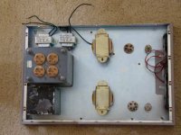
proposed amp is 6bq5 driving a 46 (depending on how well, or not, the 46 fare) , .. solid state rectification .
factors i'm looking at are minimum interference between transformer fields , the final wiring layout, and of course room to upgrade to better output iron in the future, if needed.
regarding the first pic, i also thought of a variation with the output iron swapped positions with the small driver tubes ie. toward the extreme right of the case.
), i thought i'd post my proposed layouts here . do let me know which might work better. proposed amp is 6bq5 driving a 46 (depending on how well, or not, the 46 fare) , .. solid state rectification .
factors i'm looking at are minimum interference between transformer fields , the final wiring layout, and of course room to upgrade to better output iron in the future, if needed.
regarding the first pic, i also thought of a variation with the output iron swapped positions with the small driver tubes ie. toward the extreme right of the case.
Attachments
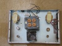
versus this ....
also, i have no idea about the current rating of the the 2.5 v filament transformer (this is for a 46 or maybe 2a3 amplifier, if the 46 doesn't have enough power for my 6" fostex 166e), .. so i'm not sure if i need one or two of them. their size is roughly 2" across. any ideas ?
thanks
also, i have no idea about the current rating of the the 2.5 v filament transformer (this is for a 46 or maybe 2a3 amplifier, if the 46 doesn't have enough power for my 6" fostex 166e), .. so i'm not sure if i need one or two of them. their size is roughly 2" across. any ideas ?
thanks
Attachments
EC8010 said:Which lump of iron is which?
sorry , i should have been more explicit
the big honking boatanchor is the power Tx (289 V and 250 V secondary taps @ about 200 - 250 mA , IIRC plus a host of high amp 6.3V taps
the black relic is a 6H / 250 mA / 80 ohm DCR choke
the two tiny silver trannys are 2.5v filament Tx
the two brass coloured Tx are for the output
of course, i could plausibly rectify 6.3 V and regulate it down to 5V DC to use for the 2 x 2.5V DHT heaters strung in series, .. not sure if it's worth it though.
Some questions-
* Where do you plan to mount the inputs?
* Will you have only a single set of inputs or are you planning a source selector switch as well?
* Related to the above- will there be a volume control and where do you plan to mount it?
* What is the second largest piece of iron in the images? I'm assuming the big one is the PTX, the smaller open frames are chokes (could be input TXs?) and the larger open frames are OPTs. That leaves me scratching my head on the other one.
So before knowing all that-
If you mount your input jacks on top, close to what I assume are the input tube sockets I like layout number 1, except I would mount the PTX on the end with the fans. Fans are noisy, electrically and audibly so I would keep them as far from the input tubes as possible. It may not be as efficient at cooling the tubes but should be quieter, and you can put a vent on the other end, now the front, to direct cooling air over the tube bases.
You can mount your input jacks and volume control on the "front" as well running the wires up over the top input tube and then down to the bottom tube between the input tubes and output tubes. That way the low signal wires are as far as possible from the AC heaters. And use shielded wire for the inputs between the volume control and the input tubes.
- Status
- This old topic is closed. If you want to reopen this topic, contact a moderator using the "Report Post" button.