Aikado Power Supply
Would anyone care to share their power supply designs for the Aikido Line Stage. JB has helped me with the design of an Aikido Headphone amp with dual outputs, one OTL and the other for a pair of Sowter 8665 output trannies.
Thanks,
dr._sleep
Would anyone care to share their power supply designs for the Aikido Line Stage. JB has helped me with the design of an Aikido Headphone amp with dual outputs, one OTL and the other for a pair of Sowter 8665 output trannies.
An externally hosted image should be here but it was not working when we last tested it.
Thanks,
dr._sleep
Hi,
dr. sleep, Aikido has no problems with power supplies so almost any power supply will do. Just find some power supply with tube rectifier and C-L-C filter design that has on the output voltage that You require and I think You will be fine....
hope this helps and best regards
p.s. 200-0-200Vac transformer into EZ81 or similar, after that 47uF to ground than 10H inductor, than 100uF to ground and I think that You might be arround 250Vdc at the end. Off course there are much better rectifier tubes that I would like to use but EZ81 and similar are the most common ones I think..... Use whatever YOu have but watch for the first cap. (not to exceed the value recomended for the used rectifire tube)...... also You can do better than above but ......") hope this would help a little bit more).
hope this would help a little bit more).
dr. sleep, Aikido has no problems with power supplies so almost any power supply will do. Just find some power supply with tube rectifier and C-L-C filter design that has on the output voltage that You require and I think You will be fine....
hope this helps and best regards
p.s. 200-0-200Vac transformer into EZ81 or similar, after that 47uF to ground than 10H inductor, than 100uF to ground and I think that You might be arround 250Vdc at the end. Off course there are much better rectifier tubes that I would like to use but EZ81 and similar are the most common ones I think..... Use whatever YOu have but watch for the first cap. (not to exceed the value recomended for the used rectifire tube)...... also You can do better than above but ......
hope this would help a little bit more).dr._sleep said:Thanks for the reply. The power supply doesn't seem to be problematic, although, I was encouraged by JB to use a 12v regulated DC filament supply.
dr._sleep
yes,yes - I thought that this is no question - recomended - of course......
- even if the tubes are indirect heated..... I use dc filament everywhere......LM317, LM338 the common choices for the regulation.....regardsGood advice I think when it pertains to a heaphone amp.I was encouraged by JB to use a 12v regulated DC filament supply.
Even though the Aikido has built in PSRR a good psu is still necessary...but like sunrise said...a simple CLC should do the job....My Aikido is still too hummy...(think it might be the transformers)...because I just quickly wanted to whip up an Aikido...
Learning how to use psud is very handy..
I have used PSUD to develop a CLC, but I'll need to add and additional RC to get the voltge down. My PT is a 300-0-300, 150 ma. It has 6.3v for the filaments and I'll take care of the filaments with a separate 12v filament tranny and regulated circuit.

Question: This is my first attempt at a regulated filament supply and the LM350K has 2 leads on the bottom, is the ground simply soldered to the case?
Question: Can I just cap off the 6.3 v leads separately and leave them unloaded?
Thanks, dr._sleep
Question: This is my first attempt at a regulated filament supply and the LM350K has 2 leads on the bottom, is the ground simply soldered to the case?
Question: Can I just cap off the 6.3 v leads separately and leave them unloaded?
Thanks, dr._sleep
dr._sleep said:I have used PSUD to develop a CLC, but I'll need to add and additional RC to get the voltge down. My PT is a 300-0-300, 150 ma. It has 6.3v for the filaments and I'll take care of the filaments with a separate 12v filament tranny and regulated circuit.
An externally hosted image should be here but it was not working when we last tested it.
Question: This is my first attempt at a regulated filament supply and the LM350K has 2 leads on the bottom, is the ground simply soldered to the case?
Question: Can I just cap off the 6.3 v leads separately and leave them unloaded?
Thanks, dr._sleep


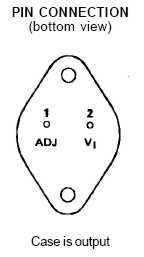
NOO.... look at the picture attached - when You look at the device from the bottom as shown at the picture - from Your left is adjust pin (ADJ) and from the right is Your input (IN). Output (OUT) is connected to the case.
I assume that You will take 6.3V from Your transformer for the rectifier tube filament and 12V from another transf. for the tube in Your line stage...?!
I don't understand the second question.... What You want to do with 6,3V and why. You don't have to connect them anywhere if You don't want to use them, or you can use them for the filaments for You rectifier tube...... I don't get it what You want so please explain.....
Im will make a schematic for Your power supply as I would like to do it now and post it when I am finished so please check this thread a little bit later please.....
there is a better way to make Your high voltage supply than just put an resistor in series (if You need lower voltage at the end).....regards
Attachments
I think he is not going to use them because he said he was going to use a seperate filament transformer. He now wants to know if he can just leave them unconnected.What You want to do with 6,3V and why
The answer is yes..you can leave them unconnected and thus unloaded...
Regards,
Bas
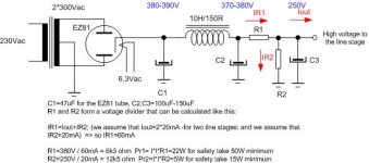
Iout is assumed to be 20mA per channel - so 40mA. And You can use other currents for IR2 but watch not to be to high with it. I assumed 20mA. You can see that Your R1 needs to be very big so I would recomend to find another transformer since Your 2*300V is to high .....
Also be aware that You have to connect You filaments of the tubes in line stage not to ground but on some voltage because You don't want to exceed approved voltage between cathode and filament. The best way to do that would be to split R2 in two resistors so that between them You have the required voltage. If You do so, watch also not to connect Your filament supply to ground. Where You connect it to ground - connect to the voltage that You have provided with split R2.
Let us know if You understood everything.....
oh - i didn't saw that mr. Bas was quicker - if You don't use EZ81 You will have smaller voltage droppout before C1 and the voltage on C1 would be higher.......
also - if You use that schematic for one chennel than it is o.k. but for both channels i think Your LM350 would be hot. Better to run with one LM338 or two LM350 (one per channel)... My opinion... 
Also be aware that You have to connect You filaments of the tubes in line stage not to ground but on some voltage because You don't want to exceed approved voltage between cathode and filament. The best way to do that would be to split R2 in two resistors so that between them You have the required voltage. If You do so, watch also not to connect Your filament supply to ground. Where You connect it to ground - connect to the voltage that You have provided with split R2.
Let us know if You understood everything.....
oh - i didn't saw that mr. Bas was quicker - if You don't use EZ81 You will have smaller voltage droppout before C1 and the voltage on C1 would be higher.......
also - if You use that schematic for one chennel than it is o.k. but for both channels i think Your LM350 would be hot. Better to run with one LM338 or two LM350 (one per channel)... My opinion...
Attachments
regarding the heater cathode voltage
6n1p can withstand +100V and -250V and 5687 +/- 100V . So I would recomend you to split the R2 into two resistors. Upper resistor will be 8750ohm and lower resistors will be 3750ohm. When You have them in series You will still have 12k5 and between them You will have 75V. That voltage You can simply connect where You would connect ground in Your filament. But watch not to connect that LED than to ground but on that voltage also....
if I am wrong someone please correct or ad if I have forgot something.......
Thanks everyone for the input. Here is where I am now
I will not use the 6v taps on my PT for any filaments, but will use a separate 12v regulated supply and series the 6N1p's ala:
I will use the 5v tap for my HT tube rectifier, NOS, Mullard GZ 32 and I have a few 5Y3's and 5U4's I could also try.
Now I understand how to implement the LM350K, which I will mount on the rear of the chassis on a heat sink.
I'll stick with the 300-0-300, 150ma tranny unless is causes a problem being over rated and thus hard to regulate.
Thanks for the PS schematic, PSUD doesn't allow you to add a resistive voltage divider, too bad.
I'm finished punching the chassis and painting is under way. I could post some pic's later for a critical free for all.
more later,
dr._sleep
I will not use the 6v taps on my PT for any filaments, but will use a separate 12v regulated supply and series the 6N1p's ala:
An externally hosted image should be here but it was not working when we last tested it.
An externally hosted image should be here but it was not working when we last tested it.
I will use the 5v tap for my HT tube rectifier, NOS, Mullard GZ 32 and I have a few 5Y3's and 5U4's I could also try.
Now I understand how to implement the LM350K, which I will mount on the rear of the chassis on a heat sink.
I'll stick with the 300-0-300, 150ma tranny unless is causes a problem being over rated and thus hard to regulate.
Thanks for the PS schematic, PSUD doesn't allow you to add a resistive voltage divider, too bad.
I'm finished punching the chassis and painting is under way. I could post some pic's later for a critical free for all.
more later,
dr._sleep
dr._sleep said:
Now I understand how to implement the LM350K, which I will mount on the rear of the chassis on a heat sink.
I'll stick with the 300-0-300, 150ma tranny unless is causes a problem being over rated and thus hard to regulate.
Thanks for the PS schematic, PSUD doesn't allow you to add a resistive voltage divider, too bad.
more later,
dr._sleep
watch that You isolate LM350 from the chasis and the heatsink...
300-0-300 will be a problem in my opinion - maybe You could do some tube regulated power supply (or maybe with fets or something) so that You lose Your voltage there - in that way You could gain "clean" power supply and loose voltage.... If You use voltage divider - You can calculate the values with the formulas that I have given You in that picture so it wouldn't be to hard.... but the power ratigns would be enormous for them so I don't think it is a good idea ......
let us know what turns out and happy diy
best regards
Re: Aikado Power Supply
Thanks to all that answered my questions on this project.
I decided to forego the regulated 12v dc thingy (even though I bought all the components), and run the filaments at 6.3 volts ac and rely on the design to manage the noise problem.
All I can say is do this if you are interested in building a completely silent, hum and hiss wise, full frequency, craps load of headroom, tubed headphone amp...do this.
Thanks to John Broskie for taking the time to help me understand the circuit and how to implement it.
This thing isn't even "burned in". I talking an hour after putting down the soldering iorn, I'm f###ing happy.
dr._sleep said:Would anyone care to share their power supply designs for the Aikido Line Stage. JB has helped me with the design of an Aikido Headphone amp with dual outputs, one OTL and the other for a pair of Sowter 8665 output trannies.
An externally hosted image should be here but it was not working when we last tested it.
Thanks,
dr._sleep
- Status
- This old topic is closed. If you want to reopen this topic, contact a moderator using the "Report Post" button.
- Home
- Amplifiers
- Tubes / Valves
- Aikido Power Supply