Someone posted or mailed me that they had done some simulations and had come up with some added circuitry that could further increase the inherent psrr / noise reduction.
Anyone have any suggestions?
Here is my current Aikido schematic
Anyone have any suggestions?
Here is my current Aikido schematic
An externally hosted image should be here but it was not working when we last tested it.
Hi Bas, I think that was me. I did a slew of sims before deciding against the Aikido in favour of an integrated amp and staying pure SE throughout the amplification chain.
Can't post any pics right now (at work). The concept's simple enough. Take V2 of the Ecc99 for example. Sims suggest the resistive divider network + cap forming the grid circuit can be optimized to greatly increase the stage PSRR ratio across a wide frequency range with just minor value tweaks. From memory the maximum untweaked PSRR simmed between 30 - 40 dB across a variety of tubes. In the ideal case optimizing can triple these values, though by that point it's probably hitting the limits of resisitor thermal stability and well past tube variances. In any case a doubling should be realizable.
I'll dig up the graphs and post once home tonight.
Ahhh yes...'t was you..")
I am very happy with the way it sounds, but I might just change those values to see what happens....
I am very happy with the way it sounds, but I might just change those values to see what happens....
Thanks a lot! Sounds interesting..I'll dig up the graphs and post once home tonight.
Sorry if this is a little OT....but what's with the sudden interest in line stages? Heretical, GG, Aikido.... I wouldn't think there are that many people with audio chains that actually need line stages. Are people just using the designs as front ends to light up big driver tubes?
I don't know why..... I guess the sudden interest is just coincidental.
I guess..many are thinking of getting one for their gainclone..not really necessary I suppose. In my case it just a journey...a little research..I have the Raleigh Audio line stage which has 8dB gain. Now that I have the Aikido...I realize how much I needed to have more gain...
Plus the search for that magical driver stage for the 300B continues...and I would love to try the Aikido stage in that position...
Ok, first all the usual disclaimers. These are sims. I haven't built this circuit and confirmed the results with measurements. The tube models aren't mine. I'm not responsible for any damage or harm resulting from implementation of these recommendations, no animals were harmed in their production, do not employ under the influence of strong medication, etc, etc..
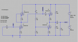
First the 'stock' circuit, the closest tried to yours but not exact.
First the 'stock' circuit, the closest tried to yours but not exact.
Attachments
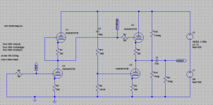
Now the 'optimized' circuit. The rational for the changes was guessing that for optimum operation the AC voltage seen by the grid of the lower output tube should approach as closely as possible the mid point between ground and B+. The lower resistor in the divider is in parallel with the lower output tube grid circuit alone and the upper resistor with the full upper tube, it stood to reason there was room for improvement. The DC blocking cap is also a factor. The same reasoning was applied to the output resistive divider.
Here's the new circuit.
Here's the new circuit.
Attachments
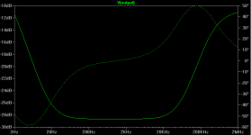
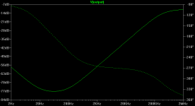
And the resulting PS rejection. The changes made don't appear to have any effect on the slope of rejection at high frequencies other than allowing it to reach further down. Increasing the size of the blocking cap lowers the frequency and further deepens the null. The good news is it appears possible to target right where PS supply noise is worst. The bad news, tuning this deep is highly sensitive. Substituting 125k for the 124.5K resistor value reduces the null to -63 dB, 120K levels off at -45 dB. Even getting close though provides significant PSRR improvement. The approach I would take is insert ten-turn pots wired as a variable resistors in series with those to be tuned and adjust for lowest output hum, maybe temporarily undersizing the power supply caps to make it easier.
That's what the sims suggest. It would certainly be cheap and easy to try, curious what results if you decide to give it a shot.
That's what the sims suggest. It would certainly be cheap and easy to try, curious what results if you decide to give it a shot.
Attachments
Interesting results.
I'm going to build this with my last remaining tubes, 12AX7 and 5687 just as an experiment. It may eventually end up in the front of my MOSFET hybrid amp (by Wim) if the gain is enough.
I notice your schematic is a little different from Broskie's original. You have no 1M resistor divider on the top output tube, as Broksie suggests for safety. Indeed you have 1M dividers on the output where Broksie only has 100Ks. What is that about.
The approach I would take is insert ten-turn pots wired as a variable resistors in series with those to be tuned and adjust for lowest output hum, maybe temporarily undersizing the power supply caps to make it easier.
Good idea..going to try it..Thanks for you illuminating posts..
heater said:I notice your schematic is a little different from Broskie's original. You have no 1M resistor divider on the top output tube, as Broksie suggests for safety. Indeed you have 1M dividers on the output where Broksie only has 100Ks. What is that about.
It's been so long since these were done I had to go back to Tubecad to see what you meant. It appears Broskie posted multiple versions himself. Some don't show the 1M divider on the output upper grid, others miss it on the output proper. It's also possible I was just playing around trying things at that point. The above trend seems to hold over multiple versions though. One I tried substituted a capacitive divider and high value grid resistor for the resistive divider and the general results were the same with different knee points.
Revisiting this last night yet another version was tried, shorting the blocking cap on the grid resistive divider to permit DC flow and capacitor coupling the mid point to the lower output tube grid, the latter properly referenced to ground with a resistor. Same, maybe better PSRR result after tweaking though I don't know how it affected distortion or operating points. It might be a handy alternative for loading down an LC or VR power supply.
Sounds perfect to me. Just for grins you could also try something like Dave Davenports minimal reactance psu.transformer-->tube rectifier-->10hy-->100uf (50K bleeder resistor)-->ccs(50ma)-->0D3(2x)(300V bypassed with 0.56uf russian teflon)
transformer->tube rectifier->4uF->CCS 50mA-> bleeder resistor to shunt excess current to earth..
- Status
- This old topic is closed. If you want to reopen this topic, contact a moderator using the "Report Post" button.
- Home
- Amplifiers
- Tubes / Valves
- Improving the Aikido line stage...