Attachments
Bas Horneman said:You mean like this?
Yes, that is what I was thinking. I think people would be interested in that. Even if you don't like my strapped pentode idea, there are some good octal tubes for this, I think Broskie even mentions some, so maybe a PCB that takes both octal and nonal will be more popular. Another idea is that someone might want to make monoblocks and mirror which triode in the tube is used for swapping later. It's just my opinion, but since Broskie only presents the circuit and not the PS and heater supplies, people will want to fall back on their experience and comfort zone for these.
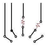
I just thought of another variation. Instead of actually leaving the PCB generic and forcing builders to put in jumpers to complete the circuit, it could be built specifically for the dual triode pinout, but with extra pads placed that would allow a builder to reconfigure by cutting traces. The extra pads could be drilled or left undrilled. Like so, on the left:
Attachments
an option for balanced output by using 2 boards will be nice too.
http://www.tubecad.com/2004/MoreAikido4.gif
I think just a couple extra solder pads will do.
http://www.tubecad.com/2004/MoreAikido4.gif
I think just a couple extra solder pads will do.
leadbelly said:I just thought of another variation. Instead of actually leaving the PCB generic and forcing builders to put in jumpers to complete the circuit, it could be built specifically for the dual triode pinout, but with extra pads placed that would allow a builder to reconfigure by cutting traces. The extra pads could be drilled or left undrilled. Like so, on the left:
I'd rather leave fiddle room by using jumpers than cutting traces. Only esthetics yes, but I like neat jobs when I can do them.
sheldon
")
Bas,
Would you please tell us what sorts of filament supply you used?
Did you use AC or DC? Did you float it or raise it for the lower and upper tubes? How much for each?
I am gathering parts now for building the aikido based on the 6SN7 circuit. I can get 4 x new Sovtek 6SN7 for AUD$48 which is about USD$36. I have built a 12B4A now which sounds quite good without any problems except that I don't like the PSU caps I have at the moment. I have not got the time the report back to this forum on the positives of my 12B4A but may do it one day when I have the time. I will use that HT supply from that preamp but have to redo the filament supply since for 4 x 6SN7 I will need 6.3v @ 2.4A. I am thinking of using using 2 x LM317 to raise the DC to different levels suitable for the lower and upper tubes. e.g. 35VDC and 180DC. Does it sound right?
Best regards,
Bill
Hallo Bill,
You can do that if you have the same tube all round like you want to do...otherwize...I suppose floating them all at say 125v would be fine.
Sure AC, and have not floated it yet. But I will in my final version..the one I built now was just "quick and dirty" to see what it would be like more or lessWould you please tell us what sorts of filament supply you used?
Sounds perfect to me.6.3v @ 2.4A. I am thinking of using using 2 x LM317 to raise the DC to different levels suitable for the lower and upper tubes. e.g. 35VDC and 180DC. Does it sound right?
You can do that if you have the same tube all round like you want to do...otherwize...I suppose floating them all at say 125v would be fine.
An externally hosted image should be here but it was not working when we last tested it.
Remarks suggestions etc?
Thanks a lot to member bonny_kjs!
I asked for the output caps to be this big because I figured the Jupiter Beeswax caps 0,47uF should be able to fit there.
Here are bonny_kjs's remark in a mail to me
One showing tracks without copper filling and
the other one with copper filling on PCB.
blank space will be filled with copper to minimize crosstalk.( as shown in one PDF file).
I had to use one jumper JI ( board member can suggest how to remove)
This is a single side board. Filament wire will be directly soldered to tube base.
If filament tracks are to be laid then I have make PCB double side which will increase the cost may be 20 to 30%. This will help in removing jumper.
I can enlarge PCB to accommodate two channels
Approximate size of single channel is 100 X 100mm to two channels 200X 100 mm
7. Noble pot can be placed on large double channel ( single side) PCB.
8. If pot can be fixed on front panel of preamp cabinet, that may be better.
9. My PCB design is not very aesthetic, but this will work very perfectly.
10. Please check all connections.
Please make suggestions.
This schematic was used.
http://www.tubecad.com/2005/January/blog0030.htm
First remarks :
Cap C1 can be a lot smaller...I used solen 0,47uF which is smaller than Jupiter.
The grid stoppers need to go right up to the grid sockets. I.e. R2 and R7.
Included is the pdf of the real scale pcb size.
http://www.tubecad.com/2005/January/blog0030.htm
First remarks :
Cap C1 can be a lot smaller...I used solen 0,47uF which is smaller than Jupiter.
The grid stoppers need to go right up to the grid sockets. I.e. R2 and R7.
Included is the pdf of the real scale pcb size.
Attachments
i just threw it together one evening
with a pile of ecc88 i had around
my first impressions were of speed
really quite breakneck with ecc88
and the silent background of course
so i rewired so's i could use ecc81 etc
which has sorted out that hurried edge
now
really natural sounding
which i had thought
of my previous pre
waiting for a pile of 5687
i've built/rebuilt several linestages
the last 417a or 6c45pi WOT
and this is so much more together
i've been running it for 2 or 3 weeks now
and every time i put it on i go WOW!!!
dave dove
btw
just checked
JB e-mailed me 30/6
just after i'd built it
must be on holiday...
- Status
- This old topic is closed. If you want to reopen this topic, contact a moderator using the "Report Post" button.
- Home
- Amplifiers
- Tubes / Valves
- Poll..anyone interested in an Aikido linestage PCB group buy?