Leclerc (Audiophile) EL34 SE
http://www.audiofanatic.it/Schemi/Tipo/Valvole/finali/pic_finali_SE/EL34SE_12AX7.jpg
Was published on the Audiophile french magazines by Michel Leclerc.
IMHO great schematic, simple good performances, cheap.
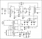
Power supply use only Poli CAP, no electrolitycs.
http://www.audiofanatic.it/Schemi/Tipo/Valvole/finali/pic_finali_SE/EL34SE_12AX7.jpg
Was published on the Audiophile french magazines by Michel Leclerc.
IMHO great schematic, simple good performances, cheap.
Power supply use only Poli CAP, no electrolitycs.
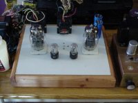
Here is a simple good sounding schematic (Not optimized for max power) I used the stuff I had in my partsbin.
http://www.basenjes.de/tubes/jbsel34.htm
http://www.basenjes.de/tubes/jbsel34.htm
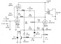
6C33C-B Schematic, and Tx winding data
Just thought I'd add my two-pence-worth,--Take a look at the scheme halfway down this thread--
http://www.diyaudio.com/forums/showthread.php?s=&threadid=56364&perpage=10&pagenumber=4
Maybe a little complicated in comparison to the others, but works well, with good dynamics.
As is, sounds pretty good, but Ive since altered it slightly by using 6SN7 at driver Mu top half and 6SL7 strapped parallel for bottom half of Mu driver--Sounds great now...........
The Tx winding data is there too if you are feeling adventurous!
Bas Horneman said:Here is a simple good sounding schematic (Not optimized for max power) I used the stuff I had in my partsbin.
http://www.basenjes.de/tubes/jbsel34.htm
well i found a power tranny to start the project but its a little small
to use with the 6c33c so im going to try bas horneman's se el34.
most of the part's like the Russian oil caps and military grade caps i can get from the tube store. ill try to stay with the same part's to see how it worked for you.
thanks..
")
Good luck!!! There is room for improvement ofcourse. But building it is a lot of fun, and I thought it sounded great. You can always tweak a little afterwards. For instance the grid stopper on the 6n1p is a little high..maybe a 100R gridstopper or even none would sound better. And maybe a little decoupling cap after the 15k voltage dropping resistor. Ofcourse the whole c4s is not that essential. You could just substitue a 33k resistor. But the C4S makes it more linear and quieter.
On 90dB speakers there is a little humm if you listen carefully with just the one choke and cap values.
It might need a preamp as well...so you could leave out the pot ...just solder in a 47k or 100k resistor...
There is room for improvement ofcourse. But building it is a lot of fun, and I thought it sounded great. You can always tweak a little afterwards. For instance the grid stopper on the 6n1p is a little high..maybe a 100R gridstopper or even none would sound better. And maybe a little decoupling cap after the 15k voltage dropping resistor. Ofcourse the whole c4s is not that essential. You could just substitue a 33k resistor. But the C4S makes it more linear and quieter.On 90dB speakers there is a little humm if you listen carefully with just the one choke and cap values.
It might need a preamp as well...so you could leave out the pot ...just solder in a 47k or 100k resistor...
Re: 6C33C-B Schematic, and Tx winding data
I am also in the process of designing a 6c33 amp with a few twists- probably a type of monkey/drd with two 6c33 opt in series per channel for regulating distortion cancellation.Anyway I wanted to refer to your power measurements.You must mean you get 30W peak and not RMS from your amp.I have played various simulations on tubecad and there is absolutely no way to get more than 16/17W RMS from one 6c33 tube and second thd is already quite high.
Alastair E said:Just thought I'd add my two-pence-worth,--Take a look at the scheme halfway down this thread--
http://www.diyaudio.com/forums/showthread.php?s=&threadid=56364&perpage=10&pagenumber=4
Maybe a little complicated in comparison to the others, but works well, with good dynamics.
As is, sounds pretty good, but Ive since altered it slightly by using 6SN7 at driver Mu top half and 6SL7 strapped parallel for bottom half of Mu driver--Sounds great now...........
The Tx winding data is there too if you are feeling adventurous!
I am also in the process of designing a 6c33 amp with a few twists- probably a type of monkey/drd with two 6c33 opt in series per channel for regulating distortion cancellation.Anyway I wanted to refer to your power measurements.You must mean you get 30W peak and not RMS from your amp.I have played various simulations on tubecad and there is absolutely no way to get more than 16/17W RMS from one 6c33 tube and second thd is already quite high.
Value at 1KHz.
The readings were taken at 1kHz, just before the onset of clipping, into a 8ohm W/W resistor. I checked twice, as I couldnt quite understand it myself........Definately 30W RMS
At lower frequencies the power isnt as high, At 20 Hz, we are at around 20W RMS at full O/P due to the limitations of the Tx
Interested in that "dynamic MOSFET cathode current sink" in one of the diagrams posted earlier,--Will do some experimentation when I get round to it!
- Status
- This old topic is closed. If you want to reopen this topic, contact a moderator using the "Report Post" button.
- Home
- Amplifiers
- Tubes / Valves
- se 6c33c or se el34 schematic