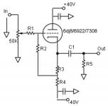
I am trying to make my first tube project, and I could use some help. Basically, this is to be a cathode folower with a volume pot for use as a unity gain preamp. I decided to use a 6dj8 as the tube as I happen to have a bunch of them, and the voltage required is reasonably low.
After looking around for examples of this circuit, I have come up with what seems to be a basic cathode follower. I am wondering if anyone could a) tell me if this is indeed a workable circuit, or if there are changes I should make, and b)help me figure out the values for R1 through R5 and C1. Even better would be help in learning how to figure out these values for myself.
At any rate, this is not meant to be the end all of fidelity, but just something that will work reasonably well as an introduction to working with tubes. That said, simple changes that will lead to large improvements would certainly be appreciated.
Thanks,
-d
Attachments
You might find this discussion useful:
http://www.diyaudio.com/forums/showthread.php?s=&threadid=58757
http://www.diyaudio.com/forums/showthread.php?s=&threadid=58757
SY said:You might find this discussion useful:
http://www.diyaudio.com/forums/showthread.php?s=&threadid=58757
Indeed. You might notice that the symbols on the schematic I posted are photoshopped off of one in that thread.
I am still having trouble going from that thread to determining values for this one, however. I think for now I'd like to experiment with the simpler design before seeing how the design in that thread changes things. The point here, after all, is not to just have the best preamp (if that was the case, I'd just buy something), but instead to learn what is going on.
If you don't have an RCA Tube Manual, get one. This is explained in gory detail.
Basically, you chose the static operating condition by sizing the big resistor down to the negative rail, then start feeling around the tube's curves to calculate the bias resistor.
Let's play with your example for a minute. 40V on the plate and a grounded grid. My, that's not a lot of excitement for that tube. But let's proceed and see if we can get away with it. The cathode is going to be somewhat positive with respect to the grid, which is at DC ground in your circuit; we don't know how much positive the cathode will be yet, but it won't be a lot, maybe a volt or two. So we can squint and approximate 40V anode-to-cathode voltage.
Now we examine the Ip-Ep curves. Assume we want to run 5mA through the tube, a pretty low value. We see that at 40V, a grid bias of roughly -0.8V is required to get that current. That's equivalent, to first order, to fixing the grid at ground and setting the cathode voltage to +0.8. Use some Ohm's Law, and the cathode resistor is R = 0.8V/5mA, which is 160 ohms.
Similarly, the bottom resistor is connected from -40 to ground and it passes the 5mA. So its value must be 40/5 = 8K.
darkfenriz said:isn't it some DC thru pot?
'noisy' option..
regards
Yeah, a cap after the wiper would be a good idea.
Hi,
Another way with an input cap inserted:
Va=70V, Ia=10mA, Vgc=-1V
R3=Vgc/Ia=100ohm
R4=(2*Vcc-Va-Vgc)/Ia=(2*40-70-1)/0.01=900ohm
R2=input impedance=100kohm
R1=grid stopper=1k
Cin=470nF/63V
C1=10uF/63V
Regards,
Milan
Instead of R4, you can use 10mA current source.
Another way with an input cap inserted:
Va=70V, Ia=10mA, Vgc=-1V
R3=Vgc/Ia=100ohm
R4=(2*Vcc-Va-Vgc)/Ia=(2*40-70-1)/0.01=900ohm
R2=input impedance=100kohm
R1=grid stopper=1k
Cin=470nF/63V
C1=10uF/63V
Regards,
Milan
Instead of R4, you can use 10mA current source.
IMO, a small change of direction is called for. The buffered level control is almost surely going to be used with a CDP. The full O/P of a CDP is 2 V. RMS, which is 5.66 V. peak to peak. So, 6 V. of grid bias is indicated. Getting that 6 V. of bias is easy. Use a 6 V. Lithium battery.
It hangs together nicely. Use a 50 KOhm pot. at the I/P. Connect the wiper of the pot. to a 100 nF. film cap. Connect the film cap. to a 560 KOhm grid leak resistor connected to the - terminal of the battery. Connect the + terminal of the battery to the triode's cathode. Select the load resistor and B+ rail voltage to be consistent with the tube's data sheet.
It hangs together nicely. Use a 50 KOhm pot. at the I/P. Connect the wiper of the pot. to a 100 nF. film cap. Connect the film cap. to a 560 KOhm grid leak resistor connected to the - terminal of the battery. Connect the + terminal of the battery to the triode's cathode. Select the load resistor and B+ rail voltage to be consistent with the tube's data sheet.
Eli, I don't follow the logic. At 6 volts of bias, the tube will need at least 200V on the plate to get going and that's going to cause some dissipation issues at any kind of reasonable current. What's the rationale for biasing that high?
You really want bipolar +/- supplies for a vacuum-tube? One thing and another, it is often simpler to run just one positive supply rail. Your plan does have the virtue of no "fatal" voltages to ground.
Given a bipolar supply: What is R3 there for? And why does R2 run to it? What is the grid voltage? Ground, or some function of negative rail voltage???
At a glance: I don't know. SY has figured it out, darkfenriz points out that there is now DC in the pot.
This is way more complicated than it needs to be!!!
As a rough first-crack, tube voltage and load-resistor voltage should be similar. More or less in certain cases, but "equal" is often a simple place to start.
Taking the +/-40V rail as given, we might think about 40V on the tube, 40V on its load resistor.
So get rid of R3 and R2. The grid is grounded through the pot. If you don't trust the pot (you shouldn't), add a 500K resistor from grid to ground.
They call it a Cathode Follower because the cathode tends to stay very near the grid. Ground the grid and the cathode will be near ground. With bipolar supplies, this meets our "equal-voltage" first-guess.
How close is the cathode to the grid? For any useful condition the Grid-Cathode voltage will be between Zero (saturated) and Vp/Mu (cut off), cathode positive of the grid, where Vp is the Plate-Cathode voltage of the tube and Mu is the amplification factor.
Mu of the 6DJ8 is about 33. We know the Grid-Plate voltage will be 40V. We don't know the Plate-Cathode voltage, except it will be between Zero and Vp/Mu less than the Grid-Plate voltage. But since Mu is 33, the P-K voltage will be only 3% less than the G-P voltage. So for a first-hack, say Vpk is 40V, 40V/33 is 1.2V. So we may write Vpk as "about 39V", and see if the "about" causes any trouble.
What is a good value for the load resistor R4?
Probably more than 2 times the plate resistance (Rp), especially the Rp shown on the data-sheet which is taken at very favorable conditions (reasonable plate voltage and high plate current). Data-sheet shows about Rp=2K5-3K. You could go 5K resistor, but you are close to saturation; also the plate current will be fairly high.
Usually less than the load resistance, IF you need large voltage swing. However in this case you only need 3 or 4 volts of signal swing, which is "small" even compared with the "no excitement" 40V supply. To check the swing, assume the tube goes to cut-off, assume all caps hold their charge. To get 4V across 10K with a 40V supply, 0.4mA, figure the load resistor gets 40V-4V= 36V, and 36V/0.4mA= 90K. You "could" use a 90K resistor. But you really don't want to come close to cut-off; use a smaller resistor.
(Note that while standard HiFi load is 10K, if you run cables longer than 30 feet or need full power at supersonic frequencies, you may need to consider a reactive load lower than 10K. But ~10K works for most home HiFi.)
So pick a number between 5K and 90K. Geometric mean is 21K2; round-off to 22K standard value.
We have 40V-41V across 22K, which on my sliderule gives exactly 2mA. Squinting into the corner of the 6DJ8 curves, ~39V and 2mA gives Vgk about -1.5V, so we may have 38.5V on the tube and 41.5V on the 22K resistor. This is still 2mA, on my sliderule. We may really get 1.88636mA, but that is same-as 2mA for our purposes.
Is this enough? If the tube cuts-off, the 10K load and 22K resistor will swing to about 41V*(10K/(10K+22K)) or 12V peak, we only need 4V peak (or less). If the tube saturates, its Rp is about 3K, so it pulls to 38V*((10K||22K)/(3K+(10K||22K)))= 38V*(6K875/(3K+6K875))= 26V peak, which is ample. In fact it is reasonable, with the hyper-hot 6DJ8, even at ~38Vpk, to work up around 5mA as SY suggests. 41V/5mA= 8K2; I don't have that in my drawers, but if 22K works and 8K works then 10K would work fine.
The output impedance is (1/Gm)||22K. Not the spec-sheet Gm (12,000uMhos!); at small current it is lower. I see that at 35Vpk, a 1V shift in Vgk causes a ~7mA shift in current. That says 1/Gm is 142Ω around 4mA, and 142Ω is very-very-low compared to 10K loads and 30-foot cable capacitance, so low that we don't care if this estimate is way off.
No input cap is needed unless you fear DC coming out of a source (a reasonable fear).
The output cap must pass 20Hz into 10K (actually 10K+142Ω). 1uFd will do the job with almost 3dB loss at 20Hz. The cap idle voltage is ~+1V, but note that at turn-on with cold tube the cap will see -40V. So we have the ugly choice of a very large 1uFd-5uFd 50V film-cap, or a small cheap 10uFd bipolar electrolytic.
Because that output cap has some charge, you will put a bleeder resistor at the output jack. Much larger than the 10K load, much less than cap leakage. 47K is a reasonable value.
Because the 6DJ8 is a VHF triode, and your layout skills are unknown, you will put a ~2K resistor (your R1) in series with the grid, as close as possible to the grid pin.
I think rail bypass caps are kind of a frill on this circuit, as long as your power caps are within a few feet. But they don't hurt, and can help.
> 5.66 V. peak to peak. So, 6 V. of grid bias is indicated.
Not in a cathode follower; the cathode, uh, "follows" the grid. As an extreme, you can approach Vpeak (not peak-peak) divided by Mu. In this case, more like 0.1V bias. That's indeed extreme, but SY's 0.8V bias is quite ample, and my 1.2V-1.5V bias is more about being cheap with power than any signal-handling issue.
Besides which, -6V on 6DJ8 working near 40V P-K will be in extreme cut-off.
Another way of looking at it: we have 40V of bias to hide the signal in. Battery not required.
Given a bipolar supply: What is R3 there for? And why does R2 run to it? What is the grid voltage? Ground, or some function of negative rail voltage???
At a glance: I don't know. SY has figured it out, darkfenriz points out that there is now DC in the pot.
This is way more complicated than it needs to be!!!
As a rough first-crack, tube voltage and load-resistor voltage should be similar. More or less in certain cases, but "equal" is often a simple place to start.
Taking the +/-40V rail as given, we might think about 40V on the tube, 40V on its load resistor.
So get rid of R3 and R2. The grid is grounded through the pot. If you don't trust the pot (you shouldn't), add a 500K resistor from grid to ground.
They call it a Cathode Follower because the cathode tends to stay very near the grid. Ground the grid and the cathode will be near ground. With bipolar supplies, this meets our "equal-voltage" first-guess.
How close is the cathode to the grid? For any useful condition the Grid-Cathode voltage will be between Zero (saturated) and Vp/Mu (cut off), cathode positive of the grid, where Vp is the Plate-Cathode voltage of the tube and Mu is the amplification factor.
Mu of the 6DJ8 is about 33. We know the Grid-Plate voltage will be 40V. We don't know the Plate-Cathode voltage, except it will be between Zero and Vp/Mu less than the Grid-Plate voltage. But since Mu is 33, the P-K voltage will be only 3% less than the G-P voltage. So for a first-hack, say Vpk is 40V, 40V/33 is 1.2V. So we may write Vpk as "about 39V", and see if the "about" causes any trouble.
An externally hosted image should be here but it was not working when we last tested it.
What is a good value for the load resistor R4?
Probably more than 2 times the plate resistance (Rp), especially the Rp shown on the data-sheet which is taken at very favorable conditions (reasonable plate voltage and high plate current). Data-sheet shows about Rp=2K5-3K. You could go 5K resistor, but you are close to saturation; also the plate current will be fairly high.
Usually less than the load resistance, IF you need large voltage swing. However in this case you only need 3 or 4 volts of signal swing, which is "small" even compared with the "no excitement" 40V supply. To check the swing, assume the tube goes to cut-off, assume all caps hold their charge. To get 4V across 10K with a 40V supply, 0.4mA, figure the load resistor gets 40V-4V= 36V, and 36V/0.4mA= 90K. You "could" use a 90K resistor. But you really don't want to come close to cut-off; use a smaller resistor.
(Note that while standard HiFi load is 10K, if you run cables longer than 30 feet or need full power at supersonic frequencies, you may need to consider a reactive load lower than 10K. But ~10K works for most home HiFi.)
So pick a number between 5K and 90K. Geometric mean is 21K2; round-off to 22K standard value.
We have 40V-41V across 22K, which on my sliderule gives exactly 2mA. Squinting into the corner of the 6DJ8 curves, ~39V and 2mA gives Vgk about -1.5V, so we may have 38.5V on the tube and 41.5V on the 22K resistor. This is still 2mA, on my sliderule. We may really get 1.88636mA, but that is same-as 2mA for our purposes.
Is this enough? If the tube cuts-off, the 10K load and 22K resistor will swing to about 41V*(10K/(10K+22K)) or 12V peak, we only need 4V peak (or less). If the tube saturates, its Rp is about 3K, so it pulls to 38V*((10K||22K)/(3K+(10K||22K)))= 38V*(6K875/(3K+6K875))= 26V peak, which is ample. In fact it is reasonable, with the hyper-hot 6DJ8, even at ~38Vpk, to work up around 5mA as SY suggests. 41V/5mA= 8K2; I don't have that in my drawers, but if 22K works and 8K works then 10K would work fine.
The output impedance is (1/Gm)||22K. Not the spec-sheet Gm (12,000uMhos!); at small current it is lower. I see that at 35Vpk, a 1V shift in Vgk causes a ~7mA shift in current. That says 1/Gm is 142Ω around 4mA, and 142Ω is very-very-low compared to 10K loads and 30-foot cable capacitance, so low that we don't care if this estimate is way off.
No input cap is needed unless you fear DC coming out of a source (a reasonable fear).
The output cap must pass 20Hz into 10K (actually 10K+142Ω). 1uFd will do the job with almost 3dB loss at 20Hz. The cap idle voltage is ~+1V, but note that at turn-on with cold tube the cap will see -40V. So we have the ugly choice of a very large 1uFd-5uFd 50V film-cap, or a small cheap 10uFd bipolar electrolytic.
Because that output cap has some charge, you will put a bleeder resistor at the output jack. Much larger than the 10K load, much less than cap leakage. 47K is a reasonable value.
Because the 6DJ8 is a VHF triode, and your layout skills are unknown, you will put a ~2K resistor (your R1) in series with the grid, as close as possible to the grid pin.
I think rail bypass caps are kind of a frill on this circuit, as long as your power caps are within a few feet. But they don't hurt, and can help.
> 5.66 V. peak to peak. So, 6 V. of grid bias is indicated.
Not in a cathode follower; the cathode, uh, "follows" the grid. As an extreme, you can approach Vpeak (not peak-peak) divided by Mu. In this case, more like 0.1V bias. That's indeed extreme, but SY's 0.8V bias is quite ample, and my 1.2V-1.5V bias is more about being cheap with power than any signal-handling issue.
Besides which, -6V on 6DJ8 working near 40V P-K will be in extreme cut-off.
Another way of looking at it: we have 40V of bias to hide the signal in. Battery not required.
Thanks for all of this. I am going to go do some more reading and be sure I understand all of this before I proceed much further.
In hindsight I probably should not have included the voltage. There is nothing magical about it for me (I don't have an existing +/-40V supply around), I just happened to pull it from a 6dj8 tube buffer design I had seen on a Gainclone sight. I appears that just a + voltage is more appropriate here. I'll reply back when I get further.
Thanks again,
-d
SY said:Let's play with your example for a minute. 40V on the plate and a grounded grid. My, that's not a lot of excitement for that tube.
In hindsight I probably should not have included the voltage. There is nothing magical about it for me (I don't have an existing +/-40V supply around), I just happened to pull it from a 6dj8 tube buffer design I had seen on a Gainclone sight. I appears that just a + voltage is more appropriate here. I'll reply back when I get further.
Thanks again,
-d
hi d
try this thread
http://www.diyaudio.com/forums/showthread.php?postid=271719#post271719
Federico
try this thread
http://www.diyaudio.com/forums/showthread.php?postid=271719#post271719
Federico
- Status
- Not open for further replies.
- Home
- Amplifiers
- Tubes / Valves
- Basic Cathode Follower buffer