Yes, needless to say the circuit doesn't float... the voltage readings shown conflict one another on current flow for the input/driver stage. As for the output stage, unless there is a severe imbalance in the OPT or one section of the output tube being pretty dead, it's not going to generate any output. As the author quoted it sounded good, I simply implied an incorrect schematic with the option to post a correct one.
Regards, KM
Regards, KM
Well, I'm glad you're happy with the amp as it is. In case you want to 'optimize' it, I think there's lots of people around here with some suggestions.
I suppose it is possible that the amp produces output due to mismatches within the OPT and between the output tubes, although I'm pretty sure that output power is a long, long shot from where it could be in a real PP circuit with an actual phase splitter.
I haven't figured out an explanation for your measurements on the drivers stage; there are still significant discrepancies in there.
Correction:I won´t be happy untill I understand and have a proper explanation for what is happening.The opt´s were removed from a magnavox amp,so I don´t think they are top quality.Tha valves (832a) wer purchased nos and have never beem used exept for different prototypes (one of them being a SE version you can find on the web,and yes it does work and sound good).
I´d appreciate if you have time to explain the discrepancies in the driver stage.
I´d appreciate if you have time to explain the discrepancies in the driver stage.
GJA,
Not trying to rain on anyone's parade, but there's only a few reasons for getting output from such a circuit. Note that you are trying to make a push-pull design but you don't have a push-pull drive to the control grids on the 832A, hence the reference to not having a phase inverter.
In your circuit, both halves of the 832A are driven in parallel and is running as a single-ended circuit. If both halves of the 832A are working properly and the OPT functions as a push-pull OPT, then the signal developed would cancel itself in the primary winding of the OPT.
So, to get any output, here's what could be wrong:
1- one of the two sections in the 832A is either dead or not working very well.
2- the OPT is very poorly balanced on the primary winding, is connected wrong or it's not a push-pull OPT.
3- the OPT has an open side which prevents one half of the output stage from functioning.
I would suggest doing some basic reading on vacuum-tube amplifiers and design. As noted earlier, you could also look at one of the functioning push-pull 832A designs online. There are plenty of resources both printed and online which can help. Try google.... hope this helps.
Regards, KM
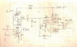
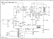
Well, I'm far from an expert myself, but here's what strikes me as odd: your 'totem pole' driver stage consists of two identical triodes on top of each other. Since both the input and the output are uncoupled for DC from the outside world through capacitors, the only DC path runs through both triodes. That means that the DC current that enters the anode of the top triode, should eventually leave the pair of triodes through the cathode resistor of the lower triode. Hence, one would expect exacty the same DC (quiescent) current to pass through the anode of the top triode, the cathode of the top triode, the anode of the bottom triode and the cathode of the bottom triode. So far basic theory.
Here's the odd thing in your observations (I refer to your most recently posted schematic): your B+ is 248V, and there's 200V on the anode of the uppermost triode of the totem pole. This means that through the 100k resistor, a current of ca. 0.48mA runs. But the voltage over the 2.2k cathode resistor of the upper tube is 2V (94-92V), which corresponds with 0.9mA. That's about 0.42mA more than through the anode of the upper tube! Where does that come from? Or more accurately: where do the electrons go? Then if we look at the cathode resistor of the lower tube, it seems to pass 0.45mA, which is in the same ballpark as the current through the 100k anode resistor. So that's odd, how come the other 2.2k resistor reading is so far off? Are the measurements accurate?
Also, it strikes me that in the last version of your schematic, there is a 100k resistor between B+ and the driver pair anode, while in the previous version, it was 33k. And more to the point: in the previous version, the anode was decoupled with a cap, which is absent in the latest version of the schematic. What's the story behind this?
All taken into account, it raises the question what the intended theory of operation of this driver configuration is. How did you come up with it, what were the design goals, and how does this circuit intend to achieve those goals? These questions could help optimizing things. Although it seems a good idea to tackle the driver issue only after the power stage is dealt with.
Btw, do you have an oscilloscope at hand? That would certainly be helpful to troubleshoot this amp. Because the power stage remains a mystery to me. How much power does it put out, if you measure it into a 8R dummy load at 1kHz?
Hi everyone,
Have done a bit of homework and understand (or think I do) why I was so wrong...obviously things are against proper design and theory.Another question is to find out why the actual circuit worked...but that´s another subject.Have gone back to copying ither people´s schematics,not always successfully for reasons which I still can´t explain.for ex. audiohobbyist´s ever so used schematics just never seems to work on my part of the world.Far from being an expert (as most of you might have noticed),i can follow a schematic and have built a few amps which work.with the one mentionned I just get hum,and more hum...with no output whatsoever.
will give it another try and see what happens.
Thanks everyone for being indulgent with my ignorance!
GJA,Hi everyone,
Have done a bit of homework and understand (or think I do) why I was so wrong...obviously things are against proper design and theory.Another question is to find out why the actual circuit worked...but that´s another subject.Have gone back to copying ither people´s schematics,not always successfully for reasons which I still can´t explain.for ex. audiohobbyist´s ever so used schematics just never seems to work on my part of the world.Far from being an expert (as most of you might have noticed),i can follow a schematic and have built a few amps which work.with the one mentionned I just get hum,and more hum...with no output whatsoever.
will give it another try and see what happens.
Thanks everyone for being indulgent with my ignorance!
Do not get discouraged trying to build an amp with 832a tubes. These are “historic marvels” as far as I'm concerned. I'm as new to vacuum tubes amps as you are and this one was my first try 4 years ago. After fixing a few of my mistakes, it worked fine. Just use a reliable circuit like the one of the following link and you will not be disappointed.
audio diy
My version is here :
http://tbl.site90.net/Amplis/
Good luck.
Francois Pelletier
Fpelleti again, after 11 years... The addreess provided for the 832a PP amplifier are outdated. Please refer to the following one for the right schematic. Yes, I'm still very happy with this amp.
http://www.hifi-forum.de/bild/832sch_216132.html
http://www.hifi-forum.de/bild/832sch_216132.html
fpelleti, never built this amp but had all intentions of it back in the day. Curious, do you have all the photos of your amp still out there for viewing?Fpelleti again, after 11 years... The addreess provided for the 832a PP amplifier are outdated. Please refer to the following one for the right schematic. Yes, I'm still very happy with this amp.
http://www.hifi-forum.de/bild/832sch_216132.html
Hi, I also built this aamp based on audiohobbyst circuit. (with CRC power supply filter and soviet era tubes: 6n23p and gu32) .If you interested in the look - i added pictures, very compact "baby" amp, sounds nice looks weird.
Attachments
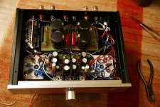
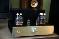
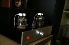
Osscar, I do have a small photo album at this address :Hi, I also built this aamp based on audiohobbyst circuit. (with CRC power supply filter and soviet era tubes: 6n23p and gu32) .If you interested in the look - i added pictures, very compact "baby" amp, sounds nice looks weird.
https://photos.app.goo.gl/HTLSNeviU3vrumFe8
I have begun to work on 2 projects I find simple yet "muscular" :Osscar, I do have a small photo album at this address :
https://photos.app.goo.gl/HTLSNeviU3vrumFe8
KT88 Parallel Single ended and 4D32 Single ended.
Regarding the 4D32 project, I find the 4D32 grid voltage circuit unnecessarily complicated with 2SC2335 transistor, zeners, etc. Could a simple resistor do the thing?
fpelleti
Attachments
- Home
- Amplifiers
- Tubes / Valves
- 832A Push Pull 5W