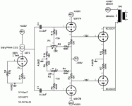
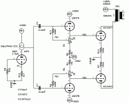
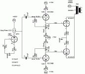
A friend of mine wants to build a 6c33c pse. We are thinking that, due to the high grid current (even when the grid is far from 0V) and the high input capacitance, a good solution should be a cathode follower direct coupled to the output tube. We've tried to design something that could even solve the bias problem for the power stage. Look at the result. I'm sure that we neglected something and this is the reason why I'm posting the scheme here and asking for your help.
Thankyou guys
Mark
Thankyou guys
Mark
Attachments
Hi Guys !
Nothing scratched my eyes at first.
I really do like the first stage with its CCS load and 400v B+, not to tell about the absence of cathode bypasses.
Heu... and what about simply bias each 6SN7 from a (adjustable) tap on its cathode resistor.
This should introduce some bootstrap releiving load from the first stage by practically hiding the grid leak resistors.
Just to chat.
Yves.
Hi Yvesm, Hi Milan.
Milan you are right...200mA for each 6c33 so 400mA in total. The 6072 with its hybrid load can provide the full mu because the current is stable and the load line straight. I think that a better solution is to change the R12 with two red leds. However...I think that with 3Vpp on the input the driver should be able to produce a 140Vpp swing. Because the amp will be two monoblock, we are thinking to change the 6072 with an ecc88 and use the second half as a common cathode preamp to make the sensibility higher.
Yvesm, what do you mean when you said: "Heu... and what about simply bias each 6SN7 from a (adjustable) tap on its cathode resistor.
This should introduce some bootstrap releiving load from the first stage by practically hiding the grid leak resistors."?
My english is not so good, could you explain it better please?
Mark
My english is not so good
Mmmh, when a Frenchy speaks to an Italian using english
I mean, just return the grid leak resistor of the 6SN7 to a tap on its cathode resistor.
For example, replace R5 by an 1K in serie with a 12K and tie the low end of R11 at the junction.
The 1K being at the cathode side and the 12K at the -200 side.
This places some positive feed back to the grid and greatly increases the input impedance because the low end of R11 is somewhat 'driven' by the cathode voltage swing.
Yves.
That's not a problem. Now we could try a soviet teflon 0.1 cap
Now I have to think to the power supply. My friend has already build a 6c33 pse and has two transformers that can provide 235Vac/500mA, 335Vac/100mA each. Do you think is possible to create a virtual gnd and a +/-200V from the 335Vac secondary and even obtain the 400V for the driver stage?
Mark
Now I have to think to the power supply. My friend has already build a 6c33 pse and has two transformers that can provide 235Vac/500mA, 335Vac/100mA each. Do you think is possible to create a virtual gnd and a +/-200V from the 335Vac secondary and even obtain the 400V for the driver stage?
Mark
We are thinking that, due to the high grid current (even when the grid is far from 0V) and the high input capacitance,
What high grid current? 6C33C this tube doesn't have high grid current and ~100kohm as gridleak is no problem to use, if you measure noticeable grid-current your tubes are probably faulty!
High capacitance? depends what you mean but due to the low mu the total Miller capacitance of a 6C33C is not much higher than tubes like 300B.
However if you want to have high bandwidth and using 6C33C in PSE I can understand the idea about using a CF to drive 6C33C but then I would probably use a 12BH7 or something similar, not just a 6SN7.
Regards Hans
Hi Hans.
What I mean is that every power tube have a small grid current. The class A manual approximation is only an approximation. Have you ever tried to use this small current to polarize small signal tubes? You can connect the cathode to gnd and a high value leak resistor from gnd to grid...and it works.
Probably due to its high transconductance, the 6c33c grid starts often to conduct before the 0V grid bias. And this point changes during the tube's life.
The miller capacitance of a 300B is not really low. I suspect that this neglected aspect ( with the fact that even in full class A the grid current is an issue...) is the reason why simple set two stage with 300B sound so slow and with bass booming! Simply the load collapses at low frequency.
You are right for the cathode follower. I'm redrawing that stage with the ecc99.
What about the voltage amplifier? I'm thinking to use an ecc8 and use one half in front of the hybrid srpp.
Mark
What I mean is that every power tube have a small grid current.
Yes, I am fully aware of that but 6C33C is not any worse than any other power tube and we are talking about currents in the uA range, to cater for this the gridleak need to have a max resistance.
You probably mean A1, i.e without gridcurrent which is what is referred to as driving the tube without positive gridcurrent.The class A manual approximation is only an approximation.
Probably due to its high transconductance, the 6C33C grid starts often to conduct before the 0V grid bias.
This is the same for all triodes but is usually not indicated in data sheets, (it is even valid for small triodes like 6SN7), the normal behavior is that grid-current is negative when the grid voltage is more negative and changes to positive at a grid voltage of between 0 and -1V.
You can find the grid-current curves describing this behavior in many tube theory books like RDH and others.
The max gridleak value seen in datasheets is given so that the negative grid current should have neglible effect on the grid-voltage.
And this point changes during the tube's life.
No, not really but the amount of grid-current for negative voltages can change.
How much anode dissipation do you run your 6C33C at? if the negative gridcurrent increases it indicates that gases are released inside the tube which will shorten lifetime very quickly, Many have experienced that 6C33C enjoy not being run at more than 2/3 of max dissipation but then life will be very long without any increased gridcurrent or any other signs of shortened life time.
Regards Hans
PS, In the OTL's I have built I have limit the anode dissipation to ~40W for each triode and I have still not experienced a tube that have failed or need to be changed, this is totally around 40 tubes. The only time I experienced any problems was when a tube failed at first switch on when there was a short between cathode and grid, but this is one tube out of 40.
DS
Hi Hans.
The working point that I've choosen is 200V/200mA for each tube. Vg=-70V So a plate dissipation of 40W, exactly the same that you have chose. 2/3 of the max power indeed.
This was chosen because I've read that this seems to be a good compromise between sound and tubes life.
The max output power is near 30W and it seems enough, I don't need much more power.
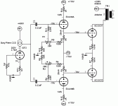
I'll add the new design that use an ecc99 instead the 6sn7
Mark
The working point that I've choosen is 200V/200mA for each tube. Vg=-70V So a plate dissipation of 40W, exactly the same that you have chose. 2/3 of the max power indeed.
This was chosen because I've read that this seems to be a good compromise between sound and tubes life.
The max output power is near 30W and it seems enough, I don't need much more power.
I'll add the new design that use an ecc99 instead the 6sn7
Mark
Attachments
On another thread I was discussing my choke loaded plate drive for the low mu output tubes. Provides lower distortion and keeps those (cough cough) solid state devices away from the signal path. And of course it can be done as a direct coupled drive, at the cost of providing a negative supply for the drive tube.
- Status
- This old topic is closed. If you want to reopen this topic, contact a moderator using the "Report Post" button.
- Home
- Amplifiers
- Tubes / Valves
- 6c33c PSE