Hello everybody,
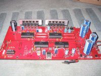
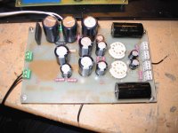
I have one original Audio Note digital board (with dig PSU). I made an SRPP output stage PCB together with the heater PSU. I'm using 300V-0V-300V toroid for the amplification and 14V-0V for the heater. Rectification for the high voltage PSU is done using 6x5-gt rectifier.
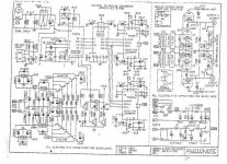
Today I connected all of this, heather voltage is fine (12.5V for two E88CC), but High Voltage that goes to the anodes is double. It is 310V and it should be around 150V. What am I doing wrong? I made the PCB same as it is in AN DAC4 schematics. Instead of one 200uf elco in the high voltage PSU I used two 100uf conected in paralel.
I have to tell you that I'm pretty inexperienced in the tube audio, so treat me like a begginer. It's probably some stupid mistake but somebody has to tell me what it is I'm doing wrong.
Here is the schematics of the DAC 4:
I have one original Audio Note digital board (with dig PSU). I made an SRPP output stage PCB together with the heater PSU. I'm using 300V-0V-300V toroid for the amplification and 14V-0V for the heater. Rectification for the high voltage PSU is done using 6x5-gt rectifier.
Today I connected all of this, heather voltage is fine (12.5V for two E88CC), but High Voltage that goes to the anodes is double. It is 310V and it should be around 150V. What am I doing wrong? I made the PCB same as it is in AN DAC4 schematics. Instead of one 200uf elco in the high voltage PSU I used two 100uf conected in paralel.
I have to tell you that I'm pretty inexperienced in the tube audio, so treat me like a begginer. It's probably some stupid mistake but somebody has to tell me what it is I'm doing wrong.
Here is the schematics of the DAC 4:
Attachments
anatech said:Your output voltage looks right for a lightly or unloaded supply. Once you start drawing current the voltage will drop.
What do you mean the voltage will drop? Will it drop down to 180V. Can I calculate this?
Yup, just calculate supply current X resistive element(s). Subtract this from the raw DC. Keep in mind the choke will not do anything much until a certian critical current level is reached (depends on choke) at which time the supply voltage will also drop. This is one reason you will find bleeder resistors in an LC ... supply.
The attached schematic earlier in your post indicates 180V, not 150V as well. You can adjust your supply voltage as required with resistive elements. Keep in mind you must draw a minimum current through the choke or the voltage rises way up. To simulate, figure out the average current draw of the circuit you are running and calculate the equivalent resistance. Connect that from the supply point to ground. You may need a 10W resistor depending on the power dissipated.
-Chris
- Status
- This old topic is closed. If you want to reopen this topic, contact a moderator using the "Report Post" button.