Hi,
I have been using Norman Koren's triode model for a while with good results.
Yesterday night I implemented the pentode equations into the same program, but the parameter fit is less straight forward that for the triode case. I found not so nice fits to the published curves using the optimized parameters for the Koren model. The fits are kind of OK, but not great. It seems that the optimization algorithm gets stuck into local minima and does not converge well.
I use the fsolve function in Matlab for the optimization.
Do you have any suggestions to improve the models? Do you use other models maybe? Or a particular optimization strategy?
Any help will be well received, just put it simple as I am no math guru.
Cheers,
Rada
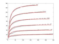
PS: I attach an example of the data from the datasheet of an EL84 (black circles) and the results of Koren's model after optimization of the parameters.
Parameters (starting value before optimization)
mu: 18.4336916000687 (19)
KP: 789.484399369241 (500)
KVB: 12.3253828438806 (500)
EX: 1.50190354423969 (1.5)
KG1: 0.998969048118742 (5)
I have been using Norman Koren's triode model for a while with good results.
Yesterday night I implemented the pentode equations into the same program, but the parameter fit is less straight forward that for the triode case. I found not so nice fits to the published curves using the optimized parameters for the Koren model. The fits are kind of OK, but not great. It seems that the optimization algorithm gets stuck into local minima and does not converge well.
I use the fsolve function in Matlab for the optimization.
Do you have any suggestions to improve the models? Do you use other models maybe? Or a particular optimization strategy?
Any help will be well received, just put it simple as I am no math guru.
Cheers,
Rada
PS: I attach an example of the data from the datasheet of an EL84 (black circles) and the results of Koren's model after optimization of the parameters.
Parameters (starting value before optimization)
mu: 18.4336916000687 (19)
KP: 789.484399369241 (500)
KVB: 12.3253828438806 (500)
EX: 1.50190354423969 (1.5)
KG1: 0.998969048118742 (5)
Attachments
The fit is "too good" over a typical audio loadline. ("Too good" because tube-to-tube variation is larger than the implied error; tubes are not precise products and there is little point in sweating 5%-10% deviations.)
The fit is poor down at low voltage and low current. Down here a lot of "small" effects become large. Grid alignment, secondary emission. You need several wacky equations to make those squiggles. However it would be highly unusual to work a tube down in this corner. If you need low current, you "logically" pick a smaller tube. (That's classical market logic; today's tube market and tube designs confound classic logic.)
My slight experimentation with the Koren Pentode seemed to give nonsensical G2 current. G2 current in an aligned-grid "beam" or "kinkless" power tube is pretty unpredictable. true. But for the "simple" triodes, G2 current tends to be a near-constant fraction of Plate current for all but the lowest plate voltages. I was seeing large G2 currents. I'm not enough of a math-head to tear into the equations and figure out why. And I may have just simulated wrong.
I've had similar problems with Koren's screen current modeling, but, hey, the price was right. I agree that this simulation isn’t too bad. You’ll want to stay away from those tetrode-like secondary emission kinks down low, as PRR says. My biggest concern is that the plate resistance looks too high (curves almost horizontal). The real tube has more of a lifted slope. I didn’t figure it, but it could easily be more than two-to-one in error in spots. That might become a big deal in an amp simulation. But that ought to be easy to fix.
These are my suggestions.
I do not know anything about Matlab, I use an Excel spreadsheet and Excel's solver function, but I think my comments should apply to your Matlab fsolve situation.
Two things :
1) with Excel what I do is run the solution, save the parameters arrived at, and the corresponding error value, and then change the parameters manually, and rerun it from that new starting point. Hopefully by thus comeing from a different direction this sort of bumps it out of the local minimum it was in, and into a lower one. I keep repeating this until I get tired of it, or until there seems to be no further progress. Now you probably have tried the same thing with your Matlab fsolve and already know this, so my second point may be more useful.
2) Try using fewer data points. You do not need so many data points. It is a general principal in parameter extraction that it is not the number of data points that matters, but the accuracy of each data point. Record lots of data points for verification of the final result if you wish, but do not use them all in your optimization algorithm ( or what I call parameter extraction ). As an example, 3 data points completely define a circle. 100 data points around the circle would not give you a more accurate circle model.
So this is what I do now. For each of 2 screen voltages, and with 4 grid voltages, I take 1 point just to the left of the knee, 1 point just to the right, 1 at the highest voltage area, and 1 in the middle. Then with plate curves with 0 grid voltage and screen voltage as the parameter, I take 4 points on each of 2 screen voltages, but obviously not the same screen voltages as used before. This is a total of 40 data points, and it is plenty.
What I find when I do this is that optimization seems to converge faster, and I can bump it out of local minima and into something close to the global minimum.
I have found that no one model fits all tubes best, so I have developed 4 or 5 that I use. But the one I use most is listed below. I have added to Koren's pentode model a feature taken from Duncan Monroes models found at Duncanamps.com. If you look at typical grid pentode curves, each grid curve comes out of the zero point in a seperate curve. Whereas with a typical beam pentode there is one line coming out of the zero point, and then each grid curve branches off that line more or less horizontally. That line I call the Diode Line, since it follows the equation for a diode, more or less. I dont know what any one else calls it, if anything. In the Duncanamps models, the current for this diode line is calculated, and it sets an upper limit on the plate current. The plate current is then calculated, and if it is less than the diode line current, then it is left alone, and that is the current used ( ie it is to the right of the knee ). But if it is more than the diode line current, then the plate current is given as equal to that diodel line current, and the "excess" current is given to the screen grid. Note that in no way do I say this is how a pentode actually works, it is just what the model is doing. So I added this same idea to Korens model. Although I started out just using it for beam tubes, I have found that it sometimes gives a better overall fit on grid pentodes as well. I am not sure why.
Here is the "hybrid" model for a 6DQ6B just to show what I am talking about. Sorry I dont have one for EL84. I have some 6BQ5s, perhaps sometime next week I can model those.
****
*
* R McLean 9 Feb 2005
* combine best features of Duncan Amps and Korens version
* 6DQ6B
* parameter extraction, from actual tube SN001, 9 February 2005
****
*
.SUBCKT 6DQ6B A S G K
+ PARAMS: Ex=1.33218884725222 Kg1=505.582374454252 Kp=20.207720434854 Kvb=11.8883545893066 Mu=6.51199341983819
+ Exd=1.45276852050569 Kd=886.375785384472 Ks=0.324360996596294 Kg=0.005
+ CCG=15P CPG1=.5P CCP=7P
Eat at 0 Value={limit(0.636*ATAN(V(A,K)/KVB),0,1)} ; arctangent shaping
Eme me 0 VALUE={PWR(LIMIT(V(A,K),0,2000),EXD)/KD} ; diode line
Egs gs 0 VALUE= {V(S,K)/KP*LOG(1+EXP((1/MU+V(G,K)/V(S,K))*KP))} ; effective voltage
Egs2 gs2 0 VALUE={(PWR(V(gs),EX)+PWRS(V(gs),EX))/(KG1*0.636)} ; total space current
G1 A K VALUE={LIMIT(V(gs2)*V(at),0,V(me))} ; plate current limited by diode line
Escrn sc 0 VALUE={KS*V(gs2)*(1.1-V(at))} ; reverse arctan shaping for screen current
G2 S K VALUE={V(sc)*LIMIT(V(S,K),0,10)/10} ; screen current
* no grid current data available so comment out the grid current line
*G3 G K VALUE={PWR(LIMIT(V(G,K)+1,0,1E6),1.5)*(1.25-V(at))*KG} ; grid current
C1 G K {CCG} ; CATHODE-GRID 1
C2 A G {CPG1} ; GRID 1-PLATE
C3 A K {CCP} ; CATHODE-PLATE
.ENDS 6DQ6B
I agree from the point of view of what is done with the final result, ie plotting load lines, and deciding on cathode bias resistors etc. You want an answer applicable to any production tube. But from the point of view of developing a model, you can never be too accurate.
Whenever possible use data from tubes that you have measured yourself. Use the data from 1 tube that you feel is typical, do not average together readings from several tubes. That may be the correct way to produce typical plate curves for a spec sheet, but it is not the right way to end up with an accurate model. When the data is averaged you end up with the curves for a mythical average tube, which does not actually exist. Its like the average family with 2.5 children. Have you ever seen 2.5 children ?
I agree, and I think the model I show above is better in that regard.
"It seems that the optimization algorithm gets stuck into local minima and does not converge well."
I do not know anything about Matlab, I use an Excel spreadsheet and Excel's solver function, but I think my comments should apply to your Matlab fsolve situation.
Two things :
1) with Excel what I do is run the solution, save the parameters arrived at, and the corresponding error value, and then change the parameters manually, and rerun it from that new starting point. Hopefully by thus comeing from a different direction this sort of bumps it out of the local minimum it was in, and into a lower one. I keep repeating this until I get tired of it, or until there seems to be no further progress. Now you probably have tried the same thing with your Matlab fsolve and already know this, so my second point may be more useful.
2) Try using fewer data points. You do not need so many data points. It is a general principal in parameter extraction that it is not the number of data points that matters, but the accuracy of each data point. Record lots of data points for verification of the final result if you wish, but do not use them all in your optimization algorithm ( or what I call parameter extraction ). As an example, 3 data points completely define a circle. 100 data points around the circle would not give you a more accurate circle model.
So this is what I do now. For each of 2 screen voltages, and with 4 grid voltages, I take 1 point just to the left of the knee, 1 point just to the right, 1 at the highest voltage area, and 1 in the middle. Then with plate curves with 0 grid voltage and screen voltage as the parameter, I take 4 points on each of 2 screen voltages, but obviously not the same screen voltages as used before. This is a total of 40 data points, and it is plenty.
What I find when I do this is that optimization seems to converge faster, and I can bump it out of local minima and into something close to the global minimum.
"Do you have any suggestions to improve the models? Do you use other models maybe? Or a particular optimization strategy?"
I have found that no one model fits all tubes best, so I have developed 4 or 5 that I use. But the one I use most is listed below. I have added to Koren's pentode model a feature taken from Duncan Monroes models found at Duncanamps.com. If you look at typical grid pentode curves, each grid curve comes out of the zero point in a seperate curve. Whereas with a typical beam pentode there is one line coming out of the zero point, and then each grid curve branches off that line more or less horizontally. That line I call the Diode Line, since it follows the equation for a diode, more or less. I dont know what any one else calls it, if anything. In the Duncanamps models, the current for this diode line is calculated, and it sets an upper limit on the plate current. The plate current is then calculated, and if it is less than the diode line current, then it is left alone, and that is the current used ( ie it is to the right of the knee ). But if it is more than the diode line current, then the plate current is given as equal to that diodel line current, and the "excess" current is given to the screen grid. Note that in no way do I say this is how a pentode actually works, it is just what the model is doing. So I added this same idea to Korens model. Although I started out just using it for beam tubes, I have found that it sometimes gives a better overall fit on grid pentodes as well. I am not sure why.
Here is the "hybrid" model for a 6DQ6B just to show what I am talking about. Sorry I dont have one for EL84. I have some 6BQ5s, perhaps sometime next week I can model those.
****
*
* R McLean 9 Feb 2005
* combine best features of Duncan Amps and Korens version
* 6DQ6B
* parameter extraction, from actual tube SN001, 9 February 2005
****
*
.SUBCKT 6DQ6B A S G K
+ PARAMS: Ex=1.33218884725222 Kg1=505.582374454252 Kp=20.207720434854 Kvb=11.8883545893066 Mu=6.51199341983819
+ Exd=1.45276852050569 Kd=886.375785384472 Ks=0.324360996596294 Kg=0.005
+ CCG=15P CPG1=.5P CCP=7P
Eat at 0 Value={limit(0.636*ATAN(V(A,K)/KVB),0,1)} ; arctangent shaping
Eme me 0 VALUE={PWR(LIMIT(V(A,K),0,2000),EXD)/KD} ; diode line
Egs gs 0 VALUE= {V(S,K)/KP*LOG(1+EXP((1/MU+V(G,K)/V(S,K))*KP))} ; effective voltage
Egs2 gs2 0 VALUE={(PWR(V(gs),EX)+PWRS(V(gs),EX))/(KG1*0.636)} ; total space current
G1 A K VALUE={LIMIT(V(gs2)*V(at),0,V(me))} ; plate current limited by diode line
Escrn sc 0 VALUE={KS*V(gs2)*(1.1-V(at))} ; reverse arctan shaping for screen current
G2 S K VALUE={V(sc)*LIMIT(V(S,K),0,10)/10} ; screen current
* no grid current data available so comment out the grid current line
*G3 G K VALUE={PWR(LIMIT(V(G,K)+1,0,1E6),1.5)*(1.25-V(at))*KG} ; grid current
C1 G K {CCG} ; CATHODE-GRID 1
C2 A G {CPG1} ; GRID 1-PLATE
C3 A K {CCP} ; CATHODE-PLATE
.ENDS 6DQ6B
"The fit is "too good" over a typical audio loadline. ("Too good" because tube-to-tube variation is larger than the implied error; tubes are not precise products and there is little point in sweating 5%-10% deviations.)"
I agree from the point of view of what is done with the final result, ie plotting load lines, and deciding on cathode bias resistors etc. You want an answer applicable to any production tube. But from the point of view of developing a model, you can never be too accurate.
Whenever possible use data from tubes that you have measured yourself. Use the data from 1 tube that you feel is typical, do not average together readings from several tubes. That may be the correct way to produce typical plate curves for a spec sheet, but it is not the right way to end up with an accurate model. When the data is averaged you end up with the curves for a mythical average tube, which does not actually exist. Its like the average family with 2.5 children. Have you ever seen 2.5 children ?
"My slight experimentation with the Koren Pentode seemed to give nonsensical G2 current."
I agree, and I think the model I show above is better in that regard.
Hi Robert,
Thanks a lot! I'll play around with your hybrid model.
About repeating the optimization using as starting conditions the parameters found in a previous optimization: my little script in Matlab does this automatically (if no convergence) and it works well for some triodes, although in most cases, a single optimization does the trick. For pentodes, however, thee is no improvement over thousands of succesive optimizations. That's the reason I turned to the forum.
I will try to use less data, as you suggested. I understand it will make stuff faster, but I am unsure about helping convergence.
Thanks again for your help.
Cheers,
Rada
PWR vs PWRS
PWR(y,x) Real power of operator, y^x
eg PWR( 2, 3 ) = 8,
PWR( -2, 3 ) = 8 even though we all know -2^3 = -8
PWRS(y,x) Real signed power of operator: |y|^x, if y>0, -|y|^x if y<0
eg PWRS( 2, 3 ) = 8
PWRS(-2, 3 ) = -8
thus
(PWR(V(gs),EX)+PWRS(V(gs),EX))
is a sort of trick to make sure the current is set to 0 when V(gs) is negative, ie the tube is cutoff. When V(gs) is positive you get 2*(V(gs)^EX) as you noted, so it is divided by 2. The factor of 2 is in built in to Kg1.
- Status
- This old topic is closed. If you want to reopen this topic, contact a moderator using the "Report Post" button.
- Home
- Amplifiers
- Tubes / Valves
- Pentode models