Thank you
valve is VT-4-C GE 211
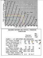
Why do there cross points on the graph not match there typical sugested.
For my amp I am advised that readings should be 950v, -45, 70ma transformer is 10k for SET mono block based on Fi 211
why such discrepancy in there graph and what I am advised by builder
what in your opinions should be my settings (ignoreing builder)
Thanks
valve is VT-4-C GE 211
Why do there cross points on the graph not match there typical sugested.
For my amp I am advised that readings should be 950v, -45, 70ma transformer is 10k for SET mono block based on Fi 211
why such discrepancy in there graph and what I am advised by builder
what in your opinions should be my settings (ignoreing builder)
Thanks
Attachments
That's the way things are ... that is the curve are just indicative and indicative are the suggested points: I found even more astonishing differences between the curves and the reality.
You would probably try different bias/anode voltages and pick up what best fits your needs. I saw lots of schematics with 211's
Ciao
Gianluca
You would probably try different bias/anode voltages and pick up what best fits your needs. I saw lots of schematics with 211's
Ciao
Gianluca
> Why do their cross points on the graph not match their typical sugested.
Tube gain/voltage/current ratios vary +/-20%. Very minor variations in dimensions, even between two tubes made by the same worker on the same day, give measurable differences.
> why such discrepancy in there graph and what I am advised by builder
Your 211 tube is different from his 211 tube. Both may be "within spec" and still be that far apart. (The tolerance on tube specs is not often shown on the commercial datasheets; the makers did not like to talk about it. The military type-specs will show some tolerance tests, but they may be at unusual operating conditions.)
> For my amp I am advised that readings should be 950v, -45, 70ma ...what in your opinions should be my settings
Well... in general.... power tubes often like to run as HOT as they can stand without grid-sag, gassing, or plate melt-down. But that does not mean you have to push to the very edge; it means you might want to avoid "too cool".
For long life, never exceed the plate rating. 950V 70mA is 66.5 Watts which is 12% on the safe side of the book rating. That is a perfectly respectable operating point.
In home use, I would not fret 75W or even 80W, nor 60W. While a 60W bias "makes less power", the difference is small to the ear. An 80W bias might give uneconomic short life in all-day every-day radio transmitter service, and I would not do that to a vintage tube for long, but it certainly won't "burn up quick" and might do home HiFi for decades. (I've found worse worse-abused tubes in old console radios, still making music.)
Do not significantly exceed the output transformer current rating; your bass will go soft and flabby. Oh, there is some margin in the rating and exceeding it is a soft slope, not a cliff. If the tranny says 70mA and it sounds good at 75mA, fine.
Likewise don't exceed the current rating of the power supply. Over-currented chokes first let more ripple through, then they run hot.
In this case, I assume you have the amp bought/built, and you don't plan any major change (different power transformer). In that case you adjust the Grid Bias until you sit at or near the design plate current. Many amps have grid-bias trimmers (because the old men knew that tubes varied a lot). If your particular 211 needs -36V or -54V to set it at 70mA, fine.
Other operating points? If you reduce the bias current, THD will rise and power will fall. If you increase current, things run hot. It may sound a wee bit better for a while, but I doubt the difference in sound is significant and going past 75mA-80mA is really cooking the plate. If you change the OPT to the nearest book-spec, 1000V and 7K6 load, bench-test power will rise a little but THD will rise faster. The 1000V 53mA 7K6 rating was good for "working" tubes that had to grind out the power with good business economics in a simpler world where 5%THD was no big deal. You could get a very slight reduction in THD by going all the way to 1250V, 60mA and 15K-20K load, but such high impedance windings have practical problems that tend to harm sound. I think a ~900V-~1000V ~70mA 10K operating point is a good pick for modern home HiFi.
Adjust grid bias to get 65-75mA cathode current.
If it is self-bias with a large hot cathode resistor: be sure you figure it right. If the raw supply is 950V, and cathode resistor drop is about 50V, there is only 900V across the tube. The plate dissipation limit is reached around 83mA. As long as the plate current is less than 83mA and not musch less than 60-70mA, I would not worry too much. Audio is not a precision art. Self-biased tubes tend to find happy operating points.
thank you very much PRR
Thank you very much PRR,
Your info was very informative and I appreciate the time and effort you put into your post.
The amps can be adjusted for bias so I will play around.
I have made load lines and watts lines etc on my graph and all seems to be okay at 70-75ma.
again thanks
Thank you very much PRR,
Your info was very informative and I appreciate the time and effort you put into your post.
The amps can be adjusted for bias so I will play around.
I have made load lines and watts lines etc on my graph and all seems to be okay at 70-75ma.
again thanks
- Status
- This old topic is closed. If you want to reopen this topic, contact a moderator using the "Report Post" button.