I have an amp with four transformers. One is a high voltage transformer. Two others are filament transformers. These three each contain two primaries, each with what looks like a center tap, and two secondaries.
Their primaries are color coded as follows.
Black–hot
Grey–ct, unconnected
Brown–connected to the browns of the other transformers but not to neutral
Red–hot on the second primary
Purple–ct, unconnected
White–neutral
The secondaries of each transformer are wired in series, each within itself as follows.
Orange on one of the secondaries–hot
Blue on the other secondary–neutral
The "inside"ends of the secondaries are tied together.
Added to this is a fourth single transformer.
It's primary is wired as
One wire to hot
The other to the joint connecting the brown wires above. Not to neutral. I can find no connection to neutral.
Again, I can find no connection to neutral for these brown wires, though the circuit diagram shows one. Nevertheless, the brown wire connection shows AC voltage with respect to the hot. This voltage is 1 volt less than the voltage read from hot to neutral.
Question 1. Why is there voltage, and why is there 1 volt difference between the browns and neutral?
Question 2. This thing has two fuses. One controls the high voltage, the first filament transformer, and the small transformer. The other goes to the second filament transformer. Now, if the first fuse (only) blows, there is some voltage emanating from the first filament transformer connected to it. That voltage causes a regulator attached to it to overheat. The only source of the voltage I can think of is from the brown wires. Remember, the second filament transformer, which also has a brown wire, is still hot, and all the browns are tied together. Am I correct that this is the source of the voltage that went to the regulator, and if so, why did the regulator overheat? (I believe that voltage was lower than normal.)
The questions seem complicated to me, but I'm guessing I just don't understand transformer theory and that they might be simple for someone out there. Or so I hope, anyway.
Depending on the answer I may have a follow up.
Thanks.
transformers 110V/220V?
Mabe a sketch would help; from your description it is hard to visualize the situation, one possibility is that this product could be factory wired for either 110 or 220 VAC
If you series two 110V transformer primaries in order to use them at 220V it is possible to put a smaller transformer across one half the primary if the smaller transformer is 110V only. Dual winding transformers have no trouble with some imbalance load on one primary to the other.
This also works for your filament transformers as the two series windings might be connected in parallel for when the unit sells in 110V countries.
There are other possibiliies, or I may have mis read your description.
I am a little confused when you say that transformer one has a white primary wire connected to neutral anfd then that there are no connections to neutral.
>>>>>Mabe a sketch would help; from your description it is hard to visualize the situation, one possibility is that this product could be factory wired for either 110 or 220 VAC
I was afraid I wasn't describing this very well.
I assume this is so. In all of the transformers, the central wire (100VAC) of each of the two primaries in a given transformer is unconnected and blocked off.
>>>If you series two 110V transformer primaries in order to use them at 220V it is possible to put a smaller transformer across one half the primary if the smaller transformer is 110V only. Dual winding transformers have no trouble with some imbalance load on one primary to the other.
That's not the issue here.
>>>>This also works for your filament transformers as the two series windings might be connected in parallel for when the unit sells in 110V countries.
Not the case here.
There are other possibiliies, or I may have mis read your description.
>>>>I am a little confused when you say that transformer one has a white primary wire connected to neutral anfd then that there are no connections to neutral.
'
Good catch. All the transformers have a white wire going to a common neutral. When I said there were "no connections" I meant that there were no connections of the brown wires to neutral. The browns are tied together and that's it for them.
Sorry. I'm not sure how to post a diagram. If I were I know this would be much easier.
I guess the question boils down to this. Let's say I have a two dual primary transformers. Let's simplify by eliminating the tapped off leads on the primary. (grey, etc)
Thus,
Black--hot of the first primary
Brown--neutral (or so I'd think) of the first primary
Red--Hot of the second primary
white--neutral of the second primary.
In all of these transformers, the Black, red and white leads are connected as espected. The brown leads of each transformer are connected only to each other. Yet I read a voltage between the black and brown that is 1 VAC less than the voltage between Black and white. Where is the refernce to neutral on the brown? Or does there need to be one? That's the first question I asked, and the more basic one. If I knew the answer to that I might be able to figure out the rest.
Thanks again. I'm sorry for the difficulty involved in describing this.
Transformer puzzle
There are some assumptions, possibly valid, in your asignment of leads to primary and secondary windings.
Do you have access to an Ohmmeter? Loads should be temporarily disconnected as well as the AC input of course. Using an Ohmeter to actually verify which wires are in fact part of a given coil will be helpful. If the Ohmmeter has a low Ohms scale you can usually spot the center tap because it will have lower Ohms to each winding "end" than the winding "ends" have to each other.
Some tranformers are made with a shield, this is usually a foil layer (non-shorting) between the primary and secondary. This layer is used to reduce EMI from getting into or out of the secondary. The shield will of course come out on a transformer lead which will be the only lead on the transformer that has no second end. When operating the apparent voltage on this lead (with no load at all) could be equal to the primary voltage or very close because of capacitive coupling. Typically this lead would connect to chassic ground.
It is painful but possible to draw a quasi schematic using Windows paint. Don't try and draw coils, just make boxes like the Europeans do for each winding and seperate them with a dotted line for the core. Label each winding end color and we've got a good communications tool. When you are finished, use "save as" to make it a JPG file for this forum. Attach it using attach file function. This way we can probably get an answer faster, if it's worth the trouble.
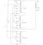
Okay, here's a diagram. There are three dual primary transformers, and one small single primary transformer. (Only the primaries are of concern here.) On each of the duals, black and red are the hot connections and White is neutral. Grey and purple are unconnected and tied off.
The concern is the brown connections. Each is the lower end of the top primary of each dual transformer. Brown is also the lower lead to T4. All four brown leads are tied together, but I can find no connection that ties them to neutral, the white leads, or anywhere else. (It is interesting to note that the diagram of a slighter later version of this design replaces T4 with the bottom half of T2 and connects these brown leads to neutral and the white leads.)
Voltage readings show the normal 117 VAC between Black or Red and White, and a volt less between Black or Red and Brown.
I have two questions.
1) From where is joint connecting the brown leads getting its neutral or near neutral reference?
Question 2 involves the fuses. Fuse 1 is tied to T1, 2 & 4. Fuse 2 is tied to T3. It should also be noted that the secondaries of T2 and 3 are tied to solid state voltage regulators.
One day Fuse 1 blew. This would cut out T1, 2, and 4, but T3 would remain operational. Indeed it was, and it was normal. What was weird was that the regulator tied to T2 was running, but very very hot.
2) Where was it getting voltage from? All I can see is that it must have been getting something from T2's brown lead that is tied to all the other browns, including the one on the operational T4. That said I assume the voltage was not what the regulator would get during normal operation, hence the overheating. Does that make sense?
Attachments
Transformer puzzle
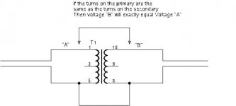
The transformers are doing what they are supposed to do. The two primaries are tied together at one end (Black and Red) if they have the same number of turns transformer action will make the other end (White and Brown) exactly equal. See my sketch
Exactly; The same effect as in my sketch was causing T1, T2 and T4 to be fed by the Black Brown windings of T3. It would appear that those windings were somewhat inadequate to run the other three transformers, resulting in inccorect voltages at their outputs so that is probably why the regulator on T2 was very hot.
If the transformer primaries are not exactly matched wiring them in parallel will get the two primaries to "fight" each other resulting in excess heat. I think the Brown leads should probably be connected to the White
originally posted by trombone
1) From where is joint connecting the brown leads getting its neutral or near neutral reference?
The transformers are doing what they are supposed to do. The two primaries are tied together at one end (Black and Red) if they have the same number of turns transformer action will make the other end (White and Brown) exactly equal. See my sketch
originally posted by trombone
2) Where was it getting voltage from? All I can see is that it must have been getting something from T2's brown lead that is tied to all the other browns, including the one on the operational T4. That said I assume the voltage was not what the regulator would get during normal operation, hence the overheating. Does that make sense?
Exactly; The same effect as in my sketch was causing T1, T2 and T4 to be fed by the Black Brown windings of T3. It would appear that those windings were somewhat inadequate to run the other three transformers, resulting in inccorect voltages at their outputs so that is probably why the regulator on T2 was very hot.
If the transformer primaries are not exactly matched wiring them in parallel will get the two primaries to "fight" each other resulting in excess heat. I think the Brown leads should probably be connected to the White
Attachments
I don't quite follow your sketch as it involves the primaries, but I do think I get what's going on from what you've said, i.e., that as long as the red and black leads of the primaries are connected to hot and white is connected to neutral, voltage will appear at any leads between them.
It would seem to me, too, that the brown leads should be connected to the white. They are in the diagram I have of a later model of this preamp (version B). In that one, there are four transformers, each with two primaries and two secondaries. Three are arranged with the secondaries tied together in series. In T2 the secondaries are tied to different circuits. In my version (A), T2 is wired like the other three, with the secondaries tied together in series. There is still a need for the separate circuit supplied by the secondary of T2 in Version A: that need is fulfilled by a separate single transformer. The normally neutral lead from that transformer is tied to the brown leads of the others. Maybe this wierd wiring of not connecting the brown leads to the whites it has to do with that.
In any case, I think you very much for your help.
transformers
I don't know if you know that the terms primary and secondary are mere conventions for the sake of dicussion. In any conventional transformer design, all the winding interact. The windings on the whole know nothing about being labeled primary or secondary.
Two windings of the same number of turns labeled "primary" will have the same voltage end to end even if only one of the two them is wired to the actual AC input power. So if you connect only one end of the second primary to the first primary the other end will match the voltage more or less exactly at the remaining end.
Connecting both primary windings to the AC input may come close to doubling the power capability of the transformer. At the least it will significantly reduce the "source" impedance of the secondaries.
Good luck on the rest of your project.
- Status
- This old topic is closed. If you want to reopen this topic, contact a moderator using the "Report Post" button.
- Home
- Amplifiers
- Tubes / Valves
- Multiple primary power transformer question