HELLO!
I need help to solve a problem.
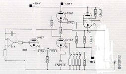
The joint principle schematic is about an hybrid power amplifier made by two stages:
- all voltage gain: vaccum tubes
- current gain: BJT.
The "rest" current is regulated by diodes, as you can see.
Now I need a solution to enter from the tubes stage to the bjt stage but please first read the following points:
- The first solution will be to enter by two capacitor on points (equal) A and B.
- The second solution will be to enter by only one capacitor, for exemple on point C.
This solution is not very good because the signal will pass through the diodes, with some non linearity. But of course it works.
NOW, the question is (number three):
1) I don't want to use capacitors to couple the two stages.
2) I don't want to use transformer to couple the two stages.
I already solve this problem!
Infact I have used a special vacuum tube stage, with a dual voltage, that comes out only with the signal and NO dc voltage.
In this case I can direct couple the vacuum tube stage to the BJT stage, entered on poit C, without capacitor... OK. It works.
BUT BUT...
as I already said, the non linearity of diodes makes the sound bad, especially low frequency.
SO I don't want to enter on point C but in the same time on points A and B
BUT...
in the BJT schematic, I CANNOT JOIN POINTS A AND B OTHERWISE I WILL BURN THE AMPLIFIER!!!
SO, WHO HAVE THE SOLUTION TO THE PROBLEM WITH PLEASE A LITTLE SCHEMATIC TO EXPLAIN ME BETTER??
I think is so simple that I cannot see it.
Thank you very much, sorry for my english, if anything is not clear please just ask.
G.M.
I need help to solve a problem.
The joint principle schematic is about an hybrid power amplifier made by two stages:
- all voltage gain: vaccum tubes
- current gain: BJT.
The "rest" current is regulated by diodes, as you can see.
Now I need a solution to enter from the tubes stage to the bjt stage but please first read the following points:
- The first solution will be to enter by two capacitor on points (equal) A and B.
- The second solution will be to enter by only one capacitor, for exemple on point C.
This solution is not very good because the signal will pass through the diodes, with some non linearity. But of course it works.
NOW, the question is (number three):
1) I don't want to use capacitors to couple the two stages.
2) I don't want to use transformer to couple the two stages.
I already solve this problem!
Infact I have used a special vacuum tube stage, with a dual voltage, that comes out only with the signal and NO dc voltage.
In this case I can direct couple the vacuum tube stage to the BJT stage, entered on poit C, without capacitor... OK. It works.
BUT BUT...
as I already said, the non linearity of diodes makes the sound bad, especially low frequency.
SO I don't want to enter on point C but in the same time on points A and B
BUT...
in the BJT schematic, I CANNOT JOIN POINTS A AND B OTHERWISE I WILL BURN THE AMPLIFIER!!!
SO, WHO HAVE THE SOLUTION TO THE PROBLEM WITH PLEASE A LITTLE SCHEMATIC TO EXPLAIN ME BETTER??
I think is so simple that I cannot see it.
Thank you very much, sorry for my english, if anything is not clear please just ask.
G.M.
Attachments
An externally hosted image should be here but it was not working when we last tested it.
> I CANNOT JOIN POINTS A AND B OTHERWISE I WILL BURN THE AMPLIFIER!!!
No. It will run cold and sound awful, but it won't burn.
Hi to everybody and thank you all.
Here you have a less principle (for the BJT stage) and a principle schematic for the tubes stage I'm using at the moment.
As I repeat, now I'm entering from the tubes stage to the BJT stage on point C of the circuit, of course without any capacitor seen that from the tubes stage we have only AC voltage output (i.e. musical signal).
It works, but I think is not the best solution.
I repeat my question:
I don't want the signal to pass through diodes, but I want it to be connected directly on points A and B, WITHOUT ANY CAPACITOR OR TRASFORMER.
But I cannot join points A and B otherwise the amplifier will work very very bad.
Thank you very much, G.M.
Attachments
Thank you to everybody!
The tubes stage as I said is a principle schematic. In the reality, there are:
- relay switching the output to ground since the DC = 0 and that works if any kind of problem (f.ex. absence of mains) occurs
- three different power for the tubes stage
- a servo circuit that help the output to be very close to 0 volt DC
So no problem for the tubes stage! It's save enough, and deliver only signal - NO DC - .
There is another delay circuit that swich on the SS stage after the tube stage is on (around 1 minute) and DC = 0.
So no problem.
There is a servo also on the SS stage for the DC voltage at output. But this is always slow (around 200mV) also without servo.
So my problem (I don't know if it could be solved, anyway) still remain.
Now I'm entring on point C on my ciruit, and everything works fine.
BUT, I would like to not pass throug diodes, and enter straigh to points A and B
(maybe using another or two BJT, with NO voltage amplification, seen that is gave exclusively by the tubes stage)
Otherwise the tube stage could be more simple and I could use two capacitor (around 2 uF) starting from the same point and entering on same time on points A and B. I know already...
Thank you, and if you could write a little schematic about...
Best wishes!
Hi!
That's is a good consideration, but I made a lot of tests.
Also the signal arrives different to points A and B, as you can see from the schematic.
Also signal through diodes can generate non linearity and can reveal very high frequencies. (also Radio frequencies!)
I report the conclusions and my experiments if you read the same "post subject" in the "Solid State" section of this forum.
Thank you very much anyway.
G.M.
- Status
- This old topic is closed. If you want to reopen this topic, contact a moderator using the "Report Post" button.
- Home
- Amplifiers
- Tubes / Valves
- HYBRID POWER AMPLIFIER - please help!