Hi!
At the moment i'm playing music with this amp...
Pre-amp is dc-filament supply.
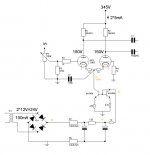
The psu is tubed (4xpy500a) 40uf-10h-300uf-1k5-82uf
B+ comes from the 300uf (377v)
B++ comes from the 82uf (356v)
As you can see it's been changed...it started with an ecc99 as splitter..now it's a longtail with ccs..it's the only tube-amp i could afford and it's changin almost every motnh (a little bit")
The 100 ohm resistors on g2 have been removed (they made the sound sound compressed, now it''s more 'open' )
Well to be honest i'm at the beginning of working with tubes and learning but would like to change the splitter once again...
You'll find it in the next post, sorry for the paint drawing....
Will this work?? will it be better??? it looks like it does, because now there are 2 'mirrors' one for voltage (equal anode resistors) and at the kathode by the second bc546b...
I heard the 2nd bc546b could be replaced by a led! is this true, this would be nice to mount on the chassis, next to the tube base as a sort of 'operating indicator'- are there benfits in doing that???
And....
The 5965 is said in this configuration to need 2v pk-pk for full-output...line=0,707v so... do i need to build a pre-amp??? (still got the ecc99's!)
For replies....please go a little slower than usual, i will understand eventually... but a little explanation why would enable me to learn of this....thnx
At the moment i'm playing music with this amp...
Pre-amp is dc-filament supply.
The psu is tubed (4xpy500a) 40uf-10h-300uf-1k5-82uf
B+ comes from the 300uf (377v)
B++ comes from the 82uf (356v)
As you can see it's been changed...it started with an ecc99 as splitter..now it's a longtail with ccs..it's the only tube-amp i could afford and it's changin almost every motnh (a little bit
The 100 ohm resistors on g2 have been removed (they made the sound sound compressed, now it''s more 'open' )
Well to be honest i'm at the beginning of working with tubes and learning but would like to change the splitter once again...
You'll find it in the next post, sorry for the paint drawing....
Will this work?? will it be better??? it looks like it does, because now there are 2 'mirrors' one for voltage (equal anode resistors) and at the kathode by the second bc546b...
I heard the 2nd bc546b could be replaced by a led! is this true, this would be nice to mount on the chassis, next to the tube base as a sort of 'operating indicator'- are there benfits in doing that???
And....
The 5965 is said in this configuration to need 2v pk-pk for full-output...line=0,707v so... do i need to build a pre-amp??? (still got the ecc99's!)
For replies....please go a little slower than usual, i will understand eventually... but a little explanation why would enable me to learn of this....thnx
Attachments
If you'll turn that auxillary supply into a negative one, you'd do well to use a cascoded pair of bipoalrs as the CS. A pair of red LEDs forward biased make a fine 3.4V reference for the CS- it's advantageous to use two of them in series, since it allows you to raise the value of the emitter resistor. That increases the output resistance of the CS, though past a certain point, you'll hit diminishing returns.
Why do you use that 100pF cap? It compromises the CS output resistance and reduces CMR and balance at very high frequencies.
Why do you use that 100pF cap? It compromises the CS output resistance and reduces CMR and balance at very high frequencies.
@sy The aux psu is already negative.... the second post is what it has to become.....it has a positive psu...
But are you telling me to use the leds as emittor resistor??, so they are NOT used as replacement of the bc546b?? why a led and not a normal resistor??
@ecc8010: so that's where the 100pf cap is for!! i wondered what it did...
i'm sorry for being slow.... but you are suggesting the 317 as 12v regulator in the new schematic...then i'll have to change the 1k resistor...(to get the 5v i need) and 2 100nf for (in-out) of the 317...
But the question remains, is the second schematic OK????
My question about the 100pF cap referred to the second schematic. I don't see what it accomplishes.
The paired LEDs I referred to are used to generate a reference voltage for the CS. So they are in the base circuit, which forces a constant current through the emitter resistor of 3.4/Re. The higher Re, the higher the output resistance at the collector. If I get to a scanner in the next little while, I'll draw you a picture.
The paired LEDs I referred to are used to generate a reference voltage for the CS. So they are in the base circuit, which forces a constant current through the emitter resistor of 3.4/Re. The higher Re, the higher the output resistance at the collector. If I get to a scanner in the next little while, I'll draw you a picture.
and the higher the output resistance at the collector the more lineair the tube will behave....
But that's just a guess of what i think you mean, i'm looking forward to see the schematic !
So, the 100p can be removed (i just left it in because it was in the schematic of the 317, thought maybe ss devices needed that.....)
Then i'll get rid of that!
But that's just a guess of what i think you mean, i'm looking forward to see the schematic !
So, the 100p can be removed (i just left it in because it was in the schematic of the 317, thought maybe ss devices needed that.....)
Then i'll get rid of that!
I've attached a quick sketch. If we assume a -15V rail, 10mA current for the CCS, and 5mA current for the LEDs, then we can quickly calculate resistor values:
Re = (3.4 - 0.7)/10 = 0.27k = 270 ohm
R1 + R2 = (15 -3.4)/ 5 = 2.32k
The last is not terribly critical. We can arbitrarily split the resistances and make R1 equal to 1.2K, R2 to 1K.
The transistors can be just about any small signal high beta type.
Re = (3.4 - 0.7)/10 = 0.27k = 270 ohm
R1 + R2 = (15 -3.4)/ 5 = 2.32k
The last is not terribly critical. We can arbitrarily split the resistances and make R1 equal to 1.2K, R2 to 1K.
The transistors can be just about any small signal high beta type.
Attachments
Thanx... I'll try this one first, because i now still have a negative supply...i see a voltage divider...and the transistors are now in series.... while the leds gives the lower one a bias voltage......
.....this is called a cascode cs??(i'll look that up
I can use it with b++ of 356 (voltage anode 150) and the same 5965 tubes???
I ask just to be sure before i build it and it blows up
very interesting and bount to keep me busy for a while before i figure out how it exactly works....
.....this is called a cascode cs??(i'll look that up
I can use it with b++ of 356 (voltage anode 150) and the same 5965 tubes???
I ask just to be sure before i build it and it blows up
very interesting and bount to keep me busy for a while before i figure out how it exactly works....
A CS doesn't care what sort of tube or B+ is involved- it will just give you a constant current within the limitations of its compliance voltage and max voltage rating of the transistors. In the cathode circuit, you're talking about max voltages above the B- rail of perhaps 25 volts. The signal is on the order of 1 volt, well within the 14V or so compliance of the CS.
Hi!
It works! cost me €5 and an hour work!!
It sounds nice...a little different...how to explain...bass is different more pronounced and i've got the idea as if the sound is more in between the speakers rather than that you can hear it coming straight from them..
thanx sy...
I already built it in (it's very tiny) now to build the other cs types...
transistors in a current mirror and machmat's (www.machmat.com ) ccs
in a nice little box with a selector switch
thanx again, bye
b
- Status
- This old topic is closed. If you want to reopen this topic, contact a moderator using the "Report Post" button.
- Home
- Amplifiers
- Tubes / Valves
- changing longtail