First of all, I am a newbie to vaccume tube design. My grandpa used to be into radio tinkering and he gave me an old RCA repairman's box full of mostly television replacement tubes and a few transformers. So this is an effort to make something useful from the parts I already have on hand.
I put together this circuit by following the Vaccume Tube Primer at boozhoundlabs.com, which was very nicely written by the way (if jason is on this forum). So please fire away at the schematic. I'm open to suggestions for or against NFB, bypass caps, or just about anything else. Thanks.
-Jared
I put together this circuit by following the Vaccume Tube Primer at boozhoundlabs.com, which was very nicely written by the way (if jason is on this forum). So please fire away at the schematic. I'm open to suggestions for or against NFB, bypass caps, or just about anything else. Thanks.
-Jared
Attachments
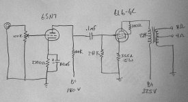
Let's see... first you know that 6L6 is a bad tube to strap in triode mode. You'll get about 1 watt. And 8k is a bit too much for plate load. And 240k is a bit too much, I would put 150k here instead, because you'll have plenty of gain with the input tube, and going high on the grid resistor will make your amp oscillate...
I would substitute the 6L6 with another tube if you got something in your junkbox
Where did this circuit come from? Have you designed it yourself?
I would substitute the 6L6 with another tube if you got something in your junkbox
Where did this circuit come from? Have you designed it yourself?
Giaime,
Yes, I designed this circuit myself.
Is a trioded 6L6 bad for sound or bad for power? I have efficient speakers and a small room, so I think I can live with low power.
Also, the data sheet indicated a power output of 1.4 watts with a very conservative Q point and 5k load line (33% of the max (30 watt) plate dissapation). The Q point for my circuit is more agressive (80-85% of the max plate diss) and the 8.8K load makes for a longer load line. The load line I plotted has more then twice the area under it than the one the data sheet reccomends, so I was thinking I might get closer to 3 watts. The output power is relative to the area under the load line right? Or have I been misinformed?
I know the 8k load is higher than normal, but I already have the transformers and their longer load line should make for less distortion. If the load proves to be a problem, I can always just hook up some 4 ohm speakers to the 8 ohm taps and have a 4.4K load.
Thanks for the tip on the grid resistor.
-Jared
Jared,
A high value of load for the 6L6 will keep distortion low.
How much drive does the 6L6 need with no cathode bypass in this circuit? I'm too lazy to look it up, but would think that the driver stage would be developing some 2H distortion getting there. Still, that's not at all unpleasant, probably sounding "well rounded".
The driver won't be able to drive a much lower grid resistor.
dhaen,
I'm sorry, I'm new at this... I don't know where to look to find how much drive a 6L6 needs. I assume you mean the 6sn7 does not have enough of an amplification factor to feed the 6L6. Giaime seemed to think there was too much power, and suggested scaling back the grid resistor. I don't know if I'm on the right track or not, but I can tell you that the grid voltage must swing + and - 25V relative to the Q point.
Also, after this amp is done I will probably be wanting to build a preamp with a RIAA filter so I can use my record player. Am I correct to assume that adding a preamp would fix the problem of the underpowered driver? Thanks.
-Jared
This link will help you calculate load lines and drive requirements:
http://members.aol.com/sbench102/po-dis.html
http://members.aol.com/sbench102/po-dis.html
100K load in the 6SN7?
Hi,
Take my comments with a grain of salt, as I am also a newbie. I have done some calculations with 6SN7-GTA and 6L6 in triode mode.
I am looking at the datashee of the 6SN7-GTA from the RCA manual. Unless the 6SN7 is really different, having a 100K load makes almost imposible a 180V B+ on that input stage.
With a 10K load is possible though, but the distortion is on the high side for an input stage I guess. I would do OK as an input for the 6L6 providing 40 to 50 V peak-to-peak of voltage swing at the plate for 4V p-t-p at the grid.
Another thing is the Miller capacitance of the 6SN7-GTA under such configuration. It is pretty high. Having a 100K input pot will reduce bandwidth quite a bit. I would go for 25K.
As far as the output stage goes, looks OK. However, for the 6L6G datasheet I am looking for (STC), they recommend 100K for the grid resistor (they mention a 500K max). You could go with a 100K resistor and a 1.5uF coupling cap. If you would like to keep the 240K resistor, use a 0.7 uF cap or so to give a better low frequency cut-off.
I would not use feedback, because the amplification factor will be reduced. With a completely bypassed cathode I am getting around 1Watt of output for a configuration like yours with under 2%THD.
Hope this helps.
Cheers,
rada
PS: I agree with the previous post. Steve's Bench will help calculate most of the stuff. The Radiotron Designer's Handbook will be even better: http://headfonz.rutgers.edu/RDH4/
- Status
- This old topic is closed. If you want to reopen this topic, contact a moderator using the "Report Post" button.
- Home
- Amplifiers
- Tubes / Valves
- My first tube amp design...check it out.